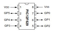
a simple 3 buttons on-off with pic12f629.

it’s written with MikroC
Step 1: The Code…

start the code with ”int”
———————————————————-
int x0,x1,y0,y1,z0,z1; ////// with this the GPIO outputs could stay on or off
void main() {
GPIO = 0x00; ////// all outputs are 0
CMCON = 0x07; ////// Disable CMCON PORT
TRISIO = 0b00111000; ////// inputs-outputs setup, 0=output 1=input (3 outputs/3 inputs)
x0=1;x1=0; ////// when the PIC starts x0=1,x1=0
y0=1;y1=0; ////// when the PIC starts y0=1,y1=0
z0=1;z1=0; ////// when the PIC starts z0=1,z1=0

while (1)
{
if ((GPIO.GP5==0)&&(x0==1)) ////// if the GPIO.GP5 grounded (pressed button) and the same time x0=1 (from the
begining of program, you see this at the previous step)
This will happen
{
x0=0; ////// the x0=1 it will be 0
x1=1; ////// the x1=0 it will be 1
GPIO.GP0=1; ////// turn the led on ( the – of the led is connected to the Ground and the + at GP0, pin 7 ) . delay_ms(600);
}
if ((GPIO.GP5==0)&&(x1==1)) ////// if the GPIO.GP5 grounded again and x1=1(from previous pressed button)
This will happen
{
x1=0; ////// x1=1 go back to 0
x0=1; ////// x0=0 go back to 1
GPIO.GP0=0; ////// now the led is off and the program wait for ((GPIO.GP5==0)&&(x0==1)) to turn on again .
delay_ms(600);
}
This is for the one button and led. You have two more. See the .txt file.
Step 3: Connection Diagram

you can use this at many projects as Latching Relay..
turn on and off circuits or devices with relay or not.
Source: Simple 3 Button On-off With 12f629 (mikroC)
