Yay – my first instructible 🙂
My 6 year old nephew wanted to have a robot to guard his room, so I decided to build one for / with him. It was supposed to have green eyes that turn red when an intruder is detected. And an alarm siren should go off. In the video you can see the final result.
Each robot needs a central circuit or “brain” which in this case is an Adafruit Trinket 5V. Hidden in the robot’s chest there is a PIR sensor to detect motion. As soon as the sensor is triggered, two green LEDs need to be switched off and two red ones are switched on – together with a piezo buzzer.
Well, that shouldn’t be too hard to program on the trinket – and it sure is a lot of fun!
By the way: The robot is powered by a 4 AA battery backpack.
This instructable is structured in several parts, so you can only build the tin robot without any electronics, and if you want to, you can add the electro stuff later. The parts are
- Building the robot body
- Putting together the electronics
- Programming the robot
Let’s get started!
Step 1: Building the Robot Body
Friends, a real robot is made from METAL, and except for the feet, I stuck to that unwritten law. Here is what I used, but feel free to use anything else:
ROBOT BODY:
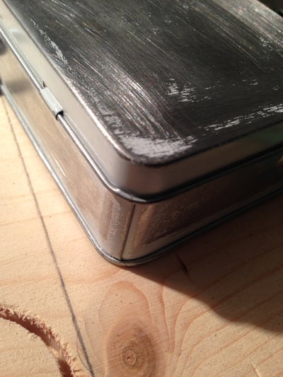
- The torso is made from a tin soap box covered by a 2.5″ hard drive plate
- The arms and legs are made from a flexible shower hose
- The head is made from a bezel covering a server’s spare power supply slot
(kindly ask your company’s IT department to search their scrap or electronics dumpster – or simply substitute the head with some other tin box… your imagination is the limit) - The only thing that is not metal are the feet, it is a piece of wood that I wrapped with silverish duck tape to make it look metallic…
Tools and materials needed:
- hack saw
- Dremel multi tool
- screw driver
- Screws and accompanying nuts, disk washers
- scrap wood
- silver Duck Tape
Add whatever you like to be on your robot! I can think of several ways already to improve the looks: Antennae, buttons, gauges, hands, …
A word of caution before you start:
Real metal looks cool on a robot, but drill holes and cut surfaces can have sharp edges. I always tried to smoothen them, file them down or cover them with tape. Wear protective gloves and safety goggles when using the Dremel multitool to cut metal.
The building process:
I am a visual guy. Please klick through the images, I attached instruction and notes there where I saw the need to explain something. I am thankful for hints if another detail image is needed or something needs to be clarified.
As I said – this is my first instructable.
Step 2: Putting Together the Electronics
Circuit Overview
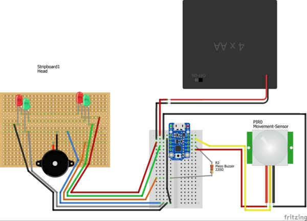
Look at the Fritzing drawing. We have three main parts we need to consider:
- A head with the LED eyes and the speaker
- The torso where the PIR sensor and the microcontroller (brain) are located
- The powersource: a 4 AA battery backback which will power the robot.
The Head
We basically need 6 wires from head to torso:
- + and Gnd for the red eyes
- + and Gnd for the green eyes
- + and Gnd for the piezo speaker.
I hid these six wires inside a “spine” in form of a scrap DB9 / RJ45 console cable that I cut apart. These cables have eight wires. Note that old Ethernet cables can also be used for this purpose – which I think is a great way of recycling old cables that would otherwise be thrown away. So you cut a convenient piece of cable, remove the outer insulation and lay bare the eight wires. Carefully reemove about 5mm of the rubber mantle insulation. Do this on both ends of the spine.
Now pick six of the wires and note down which color you want to use for + and – for the red and green LEDs as well as the piezo speaker. All of these parts will be soldered to a permanent breadboard in the head. It helps to mark on the breadboard where exactly you will locate the LEDs. Also draw a + and – where you will attach the corresponding wires. Notice that I took a protoboard all holes in a row are connected through the copper on the back side. That helped to wire the red LEDs in a row and also the green ones. Notice: it is important to interrupt the red and green LEDs’ GND lane, otherwise you would get a short circuit.
Now is a good time to solder your red and green LEDs to their final position. Double check that the GND leg (cathode) coming from the first LED is connected to the + leg (anode) of the second LED!
Now take a sharp knife or cutter to scratch away the copper that would close the loop between the 2nd LEDs cathode and the anode of the 1st LED.
Once the eyes are done, you can procede to solder the + and – of the piezo speaker; that should be easy now.
In the final step you take your spine and connect your 6 colorful wires that you noted down and solder them to the correct protoboard lane. Your robot’s head (the hardest part) is done, congratulations!
The Torso
The most important part in the torso is of course the microcontroller. It is plugged into a solderless breadboard which is glued to the tin box belly. We go on to prepare the wires on the torso end of the spine to plug into the solderless breadboard. For that purpose I soldered a breadboard-friendly tip to each of the six wires (cf. the green cable in the foto). Once you’re done with that you can plug the spine wires into the correct breadboard location one by one. Just stick to the Trinket’s Pins that are used in the program (in the next step):
- Pin 2: Piezo buzzer +
- Pin 3: Green eyes +
- Pin 4: Red eyes +
- GND: All 3 GND wires coming from the head connect to this Pin
The PIR movement sensor only has three connectors: VCC, OUT and GND. You can take female-female jumper wires to connect it to the Trinket:
- VCC on PIR —> Trinket’s 5V Pin
- OUT on PIR —> Trinket’s Pin 0
- GND on PIR —> Trinket’s GND
That is it! Now we need to power the robot.
Power Backpack
The Trinket 5V runs on (you guess it) 5 Volts. For this purpose you could either use a 5V micro USB charger which would render the robot quite immobile, or you can equip it with a backpack of 4 AA batteries of 1.5 V each which are connected in a row. This adds up to roughly 6V which is also fine for the Trinket.
If you take the power pack approach you need to solder two wires to the battery holder’s anode (preferrably red) and cathode (preferrably black). Connect the + pole (red) to the Trinket’s BAT pin and the – pole (black) to the Trinket’s GND pin.
In my design I did not (yet) include a power switch due to time constraints, but this would definitely be a valuable addition to the robot! At the moment the only way to put it to sleep is to remove one of the batteries. That will drop the current to ~4.5 V which is not enough to power the Trinket. As I said – a power switch will improve the robot a lot.
Step 3: Programming the Robot
The electronics are connected, now the robotic brain only needs to know how to use all of its parts…
The Adafruit Trinket is programmed via a USB cable that is connected to your computer. If you need help setting up the programming environment, refer to Adafruit’s very comprehensive how-to guides.
Open your Arduino programming IDE and simply import the attached sentinel-robot.ino file and upload it to your trinket. The code is quite simple with explanations
#define EYES_GREEN 3    // GPIO Pin 3
#define EYES_RED   4    // GPIO Pin 4
#define PIR 0           // Movement Sensor GPIO Pin 0
#define ALARM 2         // Piezo-buzzer GPIO Pin 2
void setup() {
  // We want to OUTPUT power to the LEDs and the buzzer,
  // We want to read the INPUT from the PIR sensor:
  pinMode (EYES_GREEN, OUTPUT);
  pinMode (EYES_RED, OUTPUT);
  pinMode (ALARM, OUTPUT);
  pinMode (PIR, INPUT);
  // initially the red eyes and the alarm are off and the green eyes are on:
  digitalWrite (PIR, LOW);
  digitalWrite (EYES_RED, LOW);
  digitalWrite (EYES_GREEN, HIGH);
  digitalWrite (ALARM, LOW);
}
// Here is a function to produce the alarm siren.
// I borrowed this from <a href="http://web.media.mit.edu/~leah/LilyPad/07_sound_code.html" rel="nofollow">  http://web.media.mit.edu/~leah/LilyPad/07_sound_c...>
void beep (unsigned chEYES_RED speakerPin, int frequencyInHertz=523, long timeInMilliseconds=500)
{
  long delayAmount = (long)(1000000 / frequencyInHertz);
  long loopTime = (long)((timeInMilliseconds * 1000) / (delayAmount * 2));
  for (int x = 0; x < loopTime; x++)
  {
    delayAmount -= 1;
    digitalWrite(speakerPin, HIGH);
    delayMicroseconds(delayAmount);
    digitalWrite(speakerPin, LOW);
    delayMicroseconds(delayAmount);
  }
}<br>void loop() {
  // this is run indefinitely:
  if (digitalRead(PIR)) {            // motion is detected
    digitalWrite(EYES_RED, HIGH);    // turn red eyes on
    digitalWrite(EYES_GREEN, LOW);   // turn green eyes off
    beep (ALARM, 1046);              // sound the alarm once
  } else {
    digitalWrite(EYES_GREEN, HIGH);  // turn green eyes back on
    digitalWrite(EYES_RED, LOW);     // switch red eyes off
  }
}
If your trinket is still connected to your robot and all of its cables, your robot should now come to life and react to movement by beeping and turning its eyes red for a few seconds until everything is “green” and quiet again.
YAY ! Have fun.
Source: Small Motion Sensing Tin Robot