Summary of Smart Home With Multiple NodeMCU ESP8266 Network With Blynk
This article details an IoT-based smart home automation project using multiple NodeMCU ESP8266 boards connected to a single Blynk account. The system allows users to control home appliances via the Blynk App over WiFi or manually through pushbuttons when the internet is unavailable. It supports real-time monitoring and independent control of relays across different rooms, ensuring reliability even during network outages.
Parts used in the Smart Home With Multiple NodeMCU ESP8266 Network:
- NodeMCU
- Relays 5v (SPDT) (4 no)
- BC547 Transistors (4 no)
- PC817 Optocuplors (4 no)
- 510-ohm 0.25-watt Resistor (4 no)
- 1k 0.25-watt Resistors (5 no)
- LED 5-mm (5 no)
- 1N4007 Diodes (5 no)
- Push Buttons (4 no) or Switches
- Terminal Connectors
- 5V DC supply
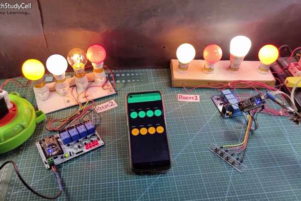
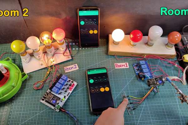
In this IoT project, I have shown how to make IoT-based Smart Home Automation using Multiple NodeMCU ESP8266 network to control all the home appliances from the pushbuttons & Blynk App. If the internet is not available, then you can control the home appliances from manual switches. During the article, I have shown all the steps to make this smart home system.
This ESP8266 NodeMCU control smart relay has the following features:
- Connect multiple NodeMCUs with the same Blynk account.
- Control home appliances with WiFi (Blynk App)
- Control home appliances with manual switches.
- Monitor real-time feedback in the Blynk App.
- Control home appliances manually without internet.
For each room, you just need a relay module & NodeMCU to make this smart home project.
Supplies:
- NodeMCU
- Relays 5v (SPDT) (4 no)
- BC547 Transistors (4 no)
- PC817 Optocuplors (4 no)
- 510-ohm 0.25-watt Resistor (4 no) (R1 – R4)
- 1k 0.25-watt Resistors (5 no) (R5 – R9)
- LED 5-mm (5 no)
- 1N4007 Diodes (5 no) (D1 – D5)
- Push Buttons (4 no) or Switches
- Terminal Connectors
- 5V DC supply
Step 1: Circuit Diagram of the ESP8266 Blynk Project
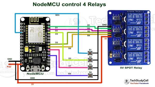
The circuit is very simple, I have used the GPIO pins D1, D2, D5 & D6 to control the 4 relays.
And the GPIO pins SD3, D3, D7 & RX connected with switches to control the 4 relays manually.
I have used the INPUT_PULLUP function in Arduino IDE instead of using the pull-up resistors.
I have used a 5V mobile charger to supply the smart relay module.
Step 2: Multiple NodeMCU ESP8266 Network
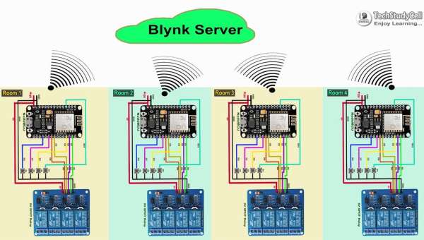
Now if you have multiple rooms, then you have to repeat the same circuit for each room.
There is no limitation on the number of NodeMCUs that can be connected.
All NodeMCU will connect to the Blynk server using the same Authenticate Token. So we can control each NodeMCU independently from Blynk App.
Step 3: Control Relays With Internet Using Blynk
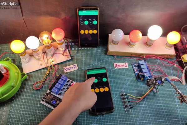
If the NodeMCUs are connected with the WiFi, then you can control the home appliances from Blynk App.
You also use multiple smartphones to control the appliances with Blynk App. For that, you have to login same Blynk account from all the smartphones. In this way, all smartphones will be sink to the Blynk server.
You can control, monitor the real-time status of the relays from anywhere in the world with the Blynk App.
If the WiFi is not available, you can control the relays from the pushbuttons.
The NodeMCU will check for the WiFi after every 3 seconds. When the WiFi is available, the NodeMCU will automatically connect with the WiFi.
Step 5: Configure the Blynk App for the Multiple NodeMCUs
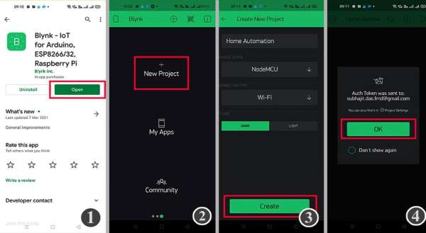
1. Install the Blynk App from the Google play store or App store. Then create an account.
2. Sign In and Tap on the New Project.
3. Give the name to the project, select NodeMCU, Connection type will be WiFi. Then tap on Create.
3. Blynk will send an authentication token to the registered email id. Tap on OK.
Step 6: Add the Button Widgets in Blynk App to Control Relays
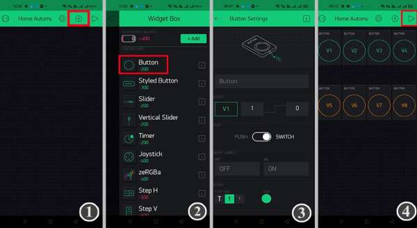
Then add 8 button widgets from the Widget Box to control the 8 relays.
Create buttons with V1,V2, V3, V4, V5, V6, V7, V8 pins to control the relays.
Select the Mode as Switch for all the buttons.
**Here I have used an active low Relay module, so to turn ON the relay we have to send “0” and “1” to turn OFF the relay.
I have used virtual pins V1, V2, V3, V4 to control the first relay module (Room-1)
And V5, V6, V7, V8 to control the second relay module (Room-2)
I have explained all the details in the tutorial video.
Step 7: Code for Blynk ESP8266 Home Automation
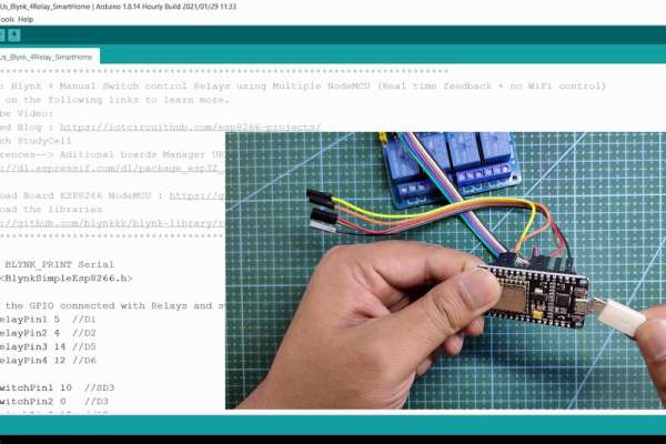
In the Tutorial video, I have explained all the steps to program the NodeMCU ESP8266 using Arduino IDE.
Before uploading the code you have to install the ESP8266 board and Blynk library.
Then enter the WiFi name, WiFi password & Blynk Auth Token in the code.
Enter the following WiFi credential and Authentication token in the code:
- WiFi Name at “WiFi Name”
- WiFi Password at “WiFi Password”
- Auth Token sent by Blynk at “AUTH TOKEN“
Select the “NodeMCU 1.0 ESP-12E” board and proper PORT. Then click on the upload button.
For each NodeMCU, you have to change the virtual pins in the code.
For the first NodeMCU, virtual pins will be V1, V2, V3, V4.
And for the second NodeMCU, virtual pins will be V5, V6, V7, V8.
Step 8: Designing the PCB
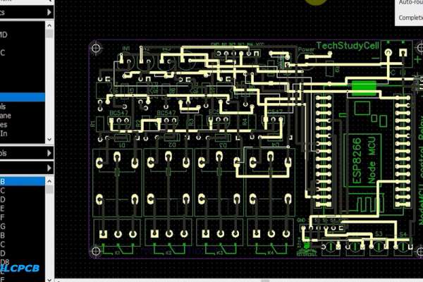
To make the circuit compact and give a professional look, I have designed the PCB after testing all the features of the smart relay module on the breadboard.
You can download the PCB Gerber file of this home automation project from the following link:
https://drive.google.com/uc?export=download&id=1Jx4D_DSV_ei1y0a82AbtxbsNhy8sjCmY
Step 9: Order the PCB

After downloading the Garber file you can easily order the PCB
1. Visit https://jlcpcb.com/RHS and Sign in / Sign up
2. Click on the QUOTE NOW button.
3 Click on the “Add your Gerber file” button. Then browse and select the Gerber file you have downloaded.
Source: Smart Home With Multiple NodeMCU ESP8266 Network With Blynk
- Can I connect multiple NodeMCUs with the same Blynk account?
Yes, you can connect multiple NodeMCUs with the same Blynk account using the same Authenticate Token. - How do I control home appliances if the internet is not available?
You can control home appliances manually using pushbuttons or switches connected to the NodeMCU. - What GPIO pins are used to control the 4 relays?
The GPIO pins D1, D2, D5, and D6 are used to control the 4 relays. - Which pins are connected for manual switch control?
The GPIO pins SD3, D3, D7, and RX are connected with switches to control the relays manually. - Does the NodeMCU check for WiFi automatically?
Yes, the NodeMCU checks for WiFi availability every 3 seconds and connects automatically when available. - How many button widgets are needed in the Blynk App for this project?
You need to add 8 button widgets from the Widget Box to control the 8 relays. - What virtual pins are assigned to the first relay module?
Virtual pins V1, V2, V3, and V4 are used to control the first relay module for Room-1. - Can I use multiple smartphones to control the appliances?
Yes, you can use multiple smartphones by logging into the same Blynk account on all devices.