Tides. In Anchorage Alaska we live on a point located between two enormous tidal bays–so big in fact that Captain Cook on his initial survey of the area thought (hopeful thinking) that this entrance would prove to be a “northwest passage”. It is shallow and all boats traversing to the port are aware of the difficulties involved with a tidal basin considered to be the second largest tide flow in the world. Strangely enough when you go through a tunnel to another port not 1/2 hour away the tidal flow is the exact opposite from the high and low tides near anchorage. Tides are dependent on the moon, sun, configuration of the ocean floor and surrounding land masses–in other words they are complicated. Old tidal clocks attempted to simplify these arrangements by reducing the periods of high and low tides to the moon movements. This works in certain locations, but is generally useless for most areas. If you look up tidal calculations you find that NOAA has great tide tables: Tide Predictions – NOAA Tides & Currents. There is lots of software out there that runs on a computer to generate these tables: JTides Home Page – Arachnoid (this guy is super smart and his web site is wonderful!) But I wanted this thing to be solar-rechargeable, low energy, go unattended for years, not rely on tons of memory, and run by a microcontroller. So I found this guys website: http://lukemiller.org/index.php/2015/11/building-a-simple-tide-clock/ He was able to take the calculations for getting tide height and reduce them into algorithms that are microcontroller size comparable.
Step 1: Gather Your Materials
So there are a couple neat parts to this build. I built a solar powered conch screamer previously: https://www.instructables.com/id/Solar-Powered-Co… didn’t like the perched solar panel as part of the design–I wanted custom cells that would become part of the instruments practicality. So you have to buy small cells from eBay or amazon and glue them together which is really fun. I also wanted to use servo control for low energy, repeatability and no need for endpoint feedback with steppers. But due to the limitations of the control to about 180 degrees I had to build a gear chain to control the 360 degree movement. For low energy I went with the Adafruit TPL5111–which has an enable to ground pin that turns off the processor unit after setting the tide-time every two hours.
Electronics/Mechanicals:
1. Adafruit TPL5111 Low Power Timer Breakout https://www.adafruit.com/product/3573
2. Adafruit Feather 32u4 Basic Proto
3. Adafruit DS3231 Precision RTC Breakout
4. Adafruit PowerBoost 500 Basic – 5V USB Boost @ 500mA from 1.8V+
5. USB / DC / Solar Lithium Ion/Polymer charger – v2 Adafruit
6. HS-225BB Servo–servo city
7. 32P, 24T C1 Spline Servo Mount Gears (Acetyl)# of teeth60T–servo city
8. 1/4″ Bore 32 Pitch Shaft Mount Pinion Gears# of teeth32T–servo city
9. 1/4″ Stainless Steel D-ShaftingLength4.00″–servo city
10. Aoshike 100pcs 0.5 V Micro mini Solar cell for solar panel 52 x 19mm/2 x 3/4 inches Polycrystalline Silicon Photovoltaic Solar Cells Sun power for DIY Cell Phone Charger–Amazon
11. 1/8 inch x 55 yds Copper Foil Tape – (3mm x 50m) – EMI Shielding Conductive Adhesive–Amazon
12. Countertop Epoxy – FX Poxy – UV Resistant Resin – 2 Quarts (Ultra Clear, 10 – 15 Sq Ft)–Lowes
13. Edge-Glued Round (Common: 1 in. x 17-3/4 in.; Actual: 1.0 in. x 17.75 in.)–Lowes
14. 18650 Lipo Battery and battery sled–Bangood
Step 2: Build Your Solar Panel
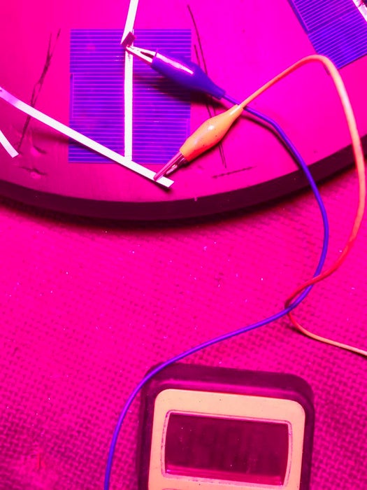
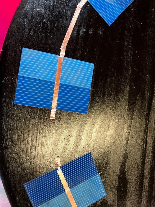
Well the first thing that you learn when you work with these solar cells is they’re fragile. I work with glass on a regular basis so I thought I would be used to fragile. But these are like potato chips–so buy some extras. Construction is basic–each cell produces 0.5 volt and you need about 6 volts to charge the lipo battery so you need 12 groups of cells in series. How many you put in parallel in each group is up to you and will determine how many mAmps you get on a sunny day. I went with three in each group–so 36 total cells. The back side of the cell is positive and the front is negative so when you join them its front to back for series and front to front and back to back for parallel. There are a million youtube videos on doing this with solder and special solder coated copper tacers but I found this not fun. So I used conductive adhesive copper strip to attach them together–it worked great. Solder the connections between groups of cells to make firm connections–this was the only point where I had failures with the sticky tape. Monitor your work carefully–putting the cell groups and then the whole unit under a grow light to check if voltage and mAmps output is correct through the whole process–failure is readily apparent. The neat thing about building with your own cells is you can design them in anyway you want–go wild with them–make a huge wave mosaic “The Great Wave off Kanagawa” or not. So when you want to lock things down connect the plus wire to the last back and minus wire to the last front and feed them through the board your building this on–I used a cheap unfinished round blank from Lowes. Surround it with a moat of tape and pour a couple layers of bartop clear epoxy to seal it all in. Then you can exhale as the chips are no longer fragile.
Step 3: Build the Servo Gear Train
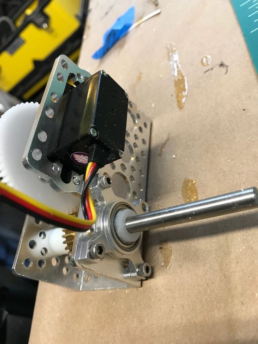
You need about a two to one ratio of gears from the servo to your output shaft so that 180 servo control will be translated into 360 movement of the hand. So I chose the appropriate size gears from servo city. You have to check and make sure that your gear hub is designed to fit your servo–there are a large variety. The servo I used was a small but not micro–I found that too tiny was not good in this case. The gears had to be rather robust too. I mounted the servo and gears in one of the servo-city housings that seem to fit together so well. They also had an included bearing which makes the action smoother but is probably not necessary.
Step 4: Electronics
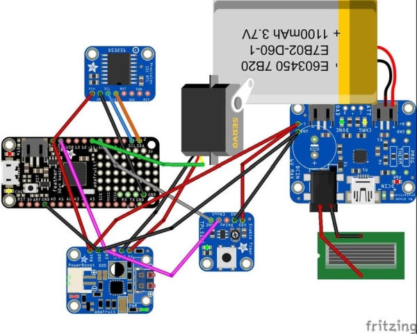
The electronics are best looked at on the Fritzing diagram. To get enough power through the possible long periods of light draught I used a 18650 battery with a sled to hold it. This was connected with a JST connector to the Adafruit Solar charge controller. The other input to this unit was the output from your beautiful solar array through a barrel connector. The output of this unit was distributed to the microcontroller, the Adafruit TPL 5111, and the boost device that powers the Servo. The 3.7 volts from the battery might be good enough for some servos but mine was stuttering quite a bit on this low power feed so I boosted it to 5 volts. The RTC is powered through the microcontroller. Pin 11 on the microcontroller is used to control the Servo. Pin 10 is used to signal the TPL 5111 that it needs to turn off power to everything by connecting the Enable pins on the microcontroller and Boost device to ground. The TPL 5111 is set to its maximum time between wakes of about 2 hours. I also put a slide switch on the TPL 5111 enable line that allowed me to trouble shoot and send new software out to the microcontroller without having it shut down. All the parts were assembled on a perf board.
Step 5: Putting It Together
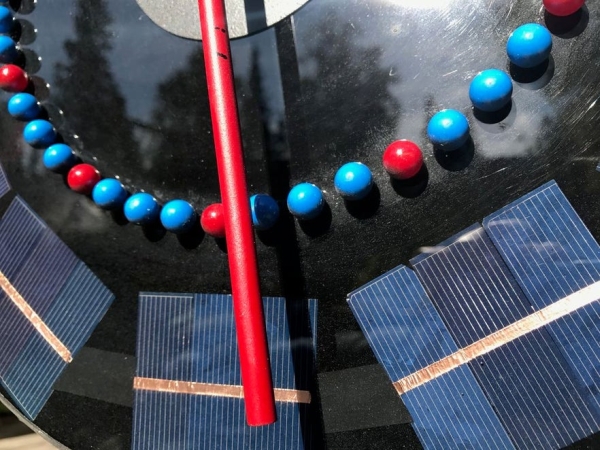
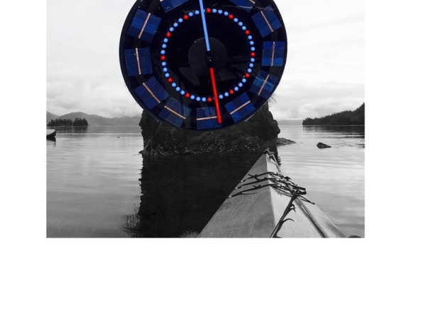
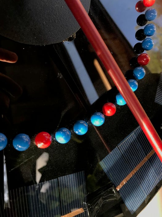
I hollowed out the back of the board to accommodate the parts. A central large hole was drilled for the servo unit to sit in. The servo gear unit was mated with a aluminum shaft pointer that was painted for RED for high tide and BLUE for low tide and large ‘map pins’ were also placed on the front surface to delineate the hours and quarter hours. No attempt was made to make the parts waterproof but this could easily be done with a rear housing.
Step 6: Programming
If you go to http://lukemiller.org/index.php/2015/11/building-a-simple-tide-clock/ you will see what a wonderful job Luke Miller did with building the infrastructure to program this device. Using the RTC you obtain the current time and then get the current water height by using an TideCalc object called myTideCalc. You can get the software bones at: http://github.com/millerlp/Tide_calculator. Every tide station has an associated software library that you must download and include with my program in a library to have it function correctly. In this case I am using the library from the Sitka sound in southeast Alaska, but you will find a variety of locations that he has set up software for. My adaptation of his software is to enable the microcontroller to find the next high or low tide when it is powered up by the TPL 5111. It does this by slowly increasing the time by 15 minute intervals and measuring when the tide changes slope from positive to negative or negative to positive signaling high or low tide and then moving the servo to the appropriate spot on the dial. Every two hours the next high or low tide is checked for and the RED or BLUE end of the clock is moved into appropriate position. When initially setting the servo position you will have to check where your servo limits are on the dial and program them into the map and constrain functions in the software. The other tricky part is using writeMicroseconds instead of servoWrite commands to control servo function as the latter does not really give you 180 control for most servos! Another note is that the software is designed for regular time not daylight savings time so there is an if statement that modifies your output depending on where you live.
Source: Solar Tide Clock