Summary of The Skittles Mini-Factory
The Skittles Mini-Factory is a self-contained unit that sorts candy by color using an ATmega1284 microcontroller. It employs an OPT101 sensor and RGB LEDs to identify five colors, then uses a solenoid to launch each Skittle onto a servo-controlled ramp leading to specific bags. Finally, a heat sealer with a nichrome wire seals the bags after every twelve candies. The system operates at approximately 0.24 Skittles per second with high color accuracy but faces mechanical challenges in dispensing.
Parts used in the Skittles Mini-Factory:
- ATmega1284 microcontroller
- OPT101 Monolithic Photodiode and Transimpedance Amplifier
- RGB LED
- Pull-type solenoid
- Position servo motor
- Velocity adjustable servo motor
- Nichrome heating wire (20 gauge)
- 12V cooling fan
- Multi-voltage power supply (3.3V, 5V, 12V)
- 8900 uF capacitor
- Transistor switch
- Flyback diode
- Current limiting resistor
- Protoboard
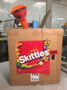
- Cardboard housing
- Clear plastic bags
Introduction
The Skittles Mini-Factory is self-contained repackaging unit that separates Skittles by color. Once separated, the Skittles are resealed in individual plastic bags. The Skittles are dispensed one at a time (either automatically or manually) onto a light sensing module. Red, green, blue, and white light are reflected off the skittle and read by the sensor. The resulting intensities are used to distinguish between the five colors (red, orange, yellow, green and purple). Once a color is detected, a solenoid shoots the skittle onto a ramp which leads the skittle to its designated bag. The ramps position is controlled by a servo and is changed depending on the skittle color. Once the bags are full, the packaging wheel rotates through a heat sealer to seal and cut the bags.
We chose this project because we liked the multidisciplinary approach it required. There were challenging elements from both an electrical and manufacturing engineering perspective. We needed accurate color sensing, precise servo control, and repeatable timing to ensure the Skittles would sort correctly. In addition, we had to build a mechanical structure capable of passing a single Skittle within fairly strict tolerances. As an added benefit, we acknowledge that many people (Alice, included) have Skittle flavor preferences which our mini-factory caters to.
High level design:
Sorting Skittles by color was chosen as a project topic to demonstrate the use of both sensors and actuation devices on an ATmega1284 microcontroller. This project has a visible and edible outcome perfect for class demonstrations.
In order to sort and move Skittles appropriately, our design calls for several different levels of actuation. These levels roughly correspond to the shelving tiers of our system. Each step moves the Skittle based on a logic related to the color of the current Skittle. The actuation components of our Skittles Mini-Factory include a pull-type solenoid, a position servo motor, and a velocity adjustable servo motor. Color sensing is performed with an OPT101 sensor and an RGB led. We are also using a cooling fan, ATmega1284 microcontroller and a multi-voltage power supply.
A Skittle enters the system through a funnel connected to the color sensing module. This module contains an OPT101 (Monolithic Photodiode and Transimpedance Amplifier) which is used along with an RGD led to determine the Skittle�s color. Each lead of the RGB LED is connected through a 220Ω resistor to a port pin on the ATmega 1284 microcontroller. In order to turn on any specific color, the system outputs a high voltage on one of the color the pin. Turning on all three pins at once produces a bluish/white light.
The LED is directed onto the Skittle with a small light block between it and the photodiode. As light hits the Skittle, certain wavelengths are reflected. The wavelength of the Skittle�s color is reflected most strongly. For example, shining a green light onto the green Skittle will reflect more light than shining a green light onto a red Skittle.
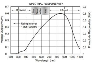
At this point, our sensor is used to gather the intensity of reflected light. Depending on the wavelength being transmitted and the reflected intensity measured, we can determine the specific color of each Skittle. The following circuit is used to power the OPT101 sensor and read an output from pin5.
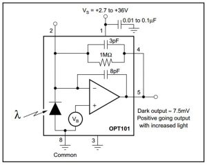
The OPT101 has several modes of operation, but we found the basic configuration sufficient for our purposes. The sensor is powered by a 5V power source directly from the microcontroller.
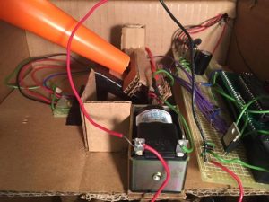
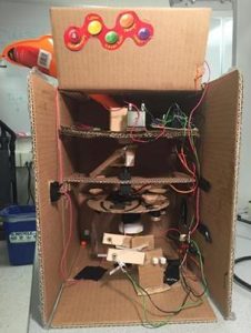
In order to increase reliability, the light intensity sensor and RGB LED were soldered onto a small breadboard and enclosed in a cardboard housing. The purpose of the cardboard housing is to isolate the sensor from ambient light, isolate the LED from directly shining onto the sensor and position each Skittle reliably over the sensor. The structure effectively accomplishes the first two tasks but fails to position the Skittle in a reliable manner.
![]()
Once a Skittle is sorted, the system pulls it off the sorting module using a pull-type solenoid. This solenoid requires. 12V and 1.2Amps of current to operate. For this reason, we were forced to purchase a larger power supply and build a capacitive discharge circuit. The circuit is composed of transistor which is connected to the microcontroller at the gate. A flyback diode is used to prevent inductive spikes. We initially powered the circuit directly from a voltage source, however, this has the potential to draw too much current from the supply. In order to limit supply current draw, we changed our circuit to discharge from a capacitor and added a current limiting resistor on the supply. An 8900 F capacitor powers our servo when the solenoid is grounded. The capacitor is connected to the 12V supply line and a T=14mS. We are not operating the solenoid faster than .5Hz, which makes this time constant sufficient to fully charge the capacitor.
The solenoid itself was taken from a surplus supply in the lab, making it impossible to get the manufacturer’s specifications. However, we do know that the solenoid is an intermittent type pull solenoid. Operating the solenoid continuously will cause it to overheat and cause damage.

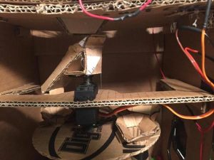
The next state of the Mini-Factory is the ramp servo component. This servo rotates a ramp to align it with five clear bags underneath. As the servo is sorted, the ramp is lined up the correct bag and the the solenoid is triggered. The servo is a position type servo which attains a position based on the duty cycle of its signal wire. The servo is operated on a 5V power supply but can accept voltages between 5 and 7.2VDC. This servo is a high torque servo and is able to deliver up to 10Kg/cm at 360Deg/Sec. The following figure details its PWM command modes:
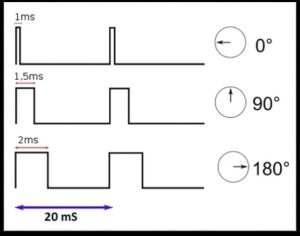
Note that the frequency of our servo must be at least 20mS to operate properly. We operated this servo at 32mS. Once the servo is positioned over a bag shoot, the Skittle drops into a bag of other similarly colored Skittles.
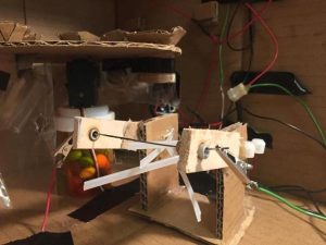
The final component of our Mini-Factory is a heat sealing device. Once 12 Skittles have been sorted, the lower wheel turns and pushes each of the five bags through a heat sealing wire. The wheel is rotated by a velocity-type servo motor. The servo must receive a PWM with a frequency of at 20mS and a duty cycle around 20%. The speed and direction of rotation of this servo can be adjusted by changing the duty cycle of the PWM.
As each bag is turning, a special pinching device closes each bag before it reaches the heating wire. This wire is a 20 gauge nichrome wire about 2 inches in length. The measured resistance of this wire is about .7Ω/in and it is connected to the 3.3V rail on our power supply. This means that our wire draws about 5 amps of current. In order to prevent unintended exposure to surrounding materials, the wire is isolated from flammable components by a metal sleeve sleeves.
In order to ventilate this system, a 12V fan is attached to the side of our cardboard enclosure. This fan is not regulated by the microcontroller but rather connected directly to the power supply.
Powering all the above devices required a dedicated power supply. We chose a tri-output supply that delivers 3.3V, 5V and 12V. The current available at 3.3V is 16 amps which is sufficient to power the heating wire and solenoid (the two components with the highest power consumption).
In order to increase reliability, the microcontroller and power amplifier circuits are soldered onto a protoboard. Likewise, the color sensor and RGD led circuit are contained on a separate protoboard.
Aesthetics were also considered in our project and colorful decorations adorn the walls of our Ming-Factory.
Background Math
It is necessary to calculate the frequency and duty cycle in order to set the PWM of both servos. The position servo requires a maximal frequency of (16 ms) or 62500 Hz. The chosen operated frequency on the servo is (32ms) or 31250 Hz. A prescaler of 256 would reduce the clock cycle to 62500 Hz. Then, setting the compare register to 10 would trigger an interrupt every 160 us. This interrupt routine will decrement a variable from 200 to 0. This corresponds to a period of 32 ms. At the beginning of each period the signal is set to high. Then according to the skittle color, the signal will be set to low after a determined pulse time. This will generate pulses every 32 ms.
Logical Structure
Pictured below is a block diagram for the code we implemented.
Program/hardware design:
The software consists of four major parts:
- Color sensing
- Aligning the servo
- Launching the solenoid
4.��� Continuous servo and heat sealing:
- Color sensing:
The color sensor hardware consists of a RGB LED and an OPT101. The LED is connected to pins B0, B1, B2 and ground. In order to determine the skittle�s color 4 different light colors are generated: white, red green and blue. The light will get reflected on the skittle back to the photodiode. The sensor output is connected to an analog to digital converter on pin A0. The ADC has an internal reference voltage of 1.1 volts and will output a number between 0 and 255 depending on the skittle color and the light generated.
Therefore, in order to determine a skittle color, the first step would require turning on the 3 led pins (to generate white light), triggering an ADC conversion and then reading the output on pin A0. Then, the same procedure will be repeated for the red green and blue light as shown in the code below:
After reading the ADC outputs, three ratios will be computed:
� RG or red to green ratio
� RB or red to blue ratio
� GB or green to blue ratio
These ratios will determine the skittle�s color. They vary within a well determined range; therefore they are bounded from below and above. The calculated ratios RG, RB and GB should fall respectively within three set of ranges to determine a color.
However, the orange and red Skittles have similar color ranges. Therefore, the white light output will differentiate both colors.
if( (RG>=2 && RG<3.2) && (RB>=4 && RB <=7.8) && (GB>=2 && GB <=2.71) && whitelight<120)
��� {
���������� fprintf(stdout, “\n\r RED\n\r\n\r”) ;
���������� redcolorflag +=1;
���������� colorflag=1;
� }
��� else if( (RG>=2.5 && RG<=3.5) && (RB>=6.1 && RB <=12) && (GB>=2.4 && GB <=3.7) && whitelight>120)
��� {
���������� fprintf(stdout, “\n\r ORANGE\n\r\n\r”) ;
���������� orangecolorflag+=1;
���������� colorflag=1;
��� }
��� else if( (RG>=1.5 && RG<=1.8) && (RB>=3.5 && RB <=6) && (GB>=2.4 && GB <=3.5))
��� {
���������� fprintf(stdout, “\n\r YELLOW\n\r\n\r”) ;
���������� yellowcolorflag+=1;
���������� colorflag=1;
��� }
��� else if( (RG>=0.1 && RG<=1.3) && (RB>=2 && RB <=2.8) && (GB>=1.75 && GB <=2.5))
��� {
���������� fprintf(stdout, “\n\r GREEN\n\r\n\r”) ;
���������� greencolorflag+=1;
���������� colorflag=1;
��� }
��� else if( (RG>=1.5 && RG<=2.4) && (RB>2.8 && RB <=3.7) && (GB>=1.4 && GB <=2.1))
��� {
���������� fprintf(stdout, “\n\r PURPLE\n\r\n\r”) ;
���������� purplecolorflag+=1;
���������� colorflag=1;
��� }
Due to variation in the skittle orientation on the light sensing module, the solenoid will not trigger until three out of five color reading belong to the same color.
for (int i=0 ;i<5 ; ){
readcolors();
guesscolors();
if(colorflag==1) //if the color is determined increment the forloop
{
i++;
colorflag=0; // reset the color flag
fprintf(stdout, “\n\r recognize color \n\r\n\r”) ;
}}
- Aligning the servo
The next step would be to position the servo correctly. As soon as a color is determined, timer 2 is turned on and a PWM signal is generated on PIN B4, long enough to position the servo at its correct position. The PWM period is around 32 ms and the pulse length vary from 480 us to 2.24 ms depending on the recognized color. Then timer two will be turned off to maintain the stability of the servo and the solenoid will be triggered.
3.������ Launching the solenoid
Triggering the solenoid requires setting port B3 to 5V for 25 ms as shown below.
void launchsolenoid(void)
{
PORTB |= (1<<PINB3);
solenoidtime1ms=25;
while(solenoidtime1ms >0);
PORTB &= (0<<PINB3);
colorflag=0;
����
���
} ����������
����
- Continuous servo and heat sealing:
The project will be completed by sealing the skittle bags. This requires heating the Nichrome wire by turning on an external switch, then rotating the continuous servo in the clockwise direction. This PWM signal will be generated using timer2 on pin D5 as follow:
hardware details:
- The hardware consists of an optical transceiver, a solenoid, two servo motors and a heat sealer.
- The optical transceiver is divided into the transmitter, an RGB LED capable of generating 3 different light colors (red, green, blue), and the receiver, the OPT101.
- The solenoid is driven by a transistor. It is connected to a 8900 uF capacitor which provides the necessary current to drive the solenoid. This reduces the amount of current being pulled directly from the power supply. The capacitor is charged from a 1.55 ohm power resistor. It is important to opto isolate the microcontroller output from the solenoid signal to prevent inductive spikes from reaching the microcontroller.
� The servo signal line is directly connected to the output pin of the microcontroller.
� Building our mini-factory out of cardboard created a number of interesting challenges. We were fortunate to find a box with great structural integrity. We divided the inside into three major sections. The first shelf housed the color-sensing module and the dispensing solenoid. The second shelf held the servo with a mounted ramp. The third section consisted of the packaging wheel mounted on a servo. The wheel has five holes for each individual skittle color bag. Making each shelf removable was particularly helpful when it came time to debug.
� Moving an individual skittle around required fairly precise construction. We preplanned each part before modelling it with cardboard. One of the main advantages of working with cardboard is its strength-to-weight ratio. The servos had no trouble moving their cardboard attachments and yet each shelf was rigid enough to sustain the weight of its components (servos, solenoid, etc.). We also benefited from the ease of repair/modification. If a part failed or needed slight modification it was simple to make the necessary changes. Though similar repairs would likely be less frequent with other materials (wood, 3D-printed ABS, etc.), they would certainly be more costly to implement.
- We were unable to control the heating wire from the microcontroller. We used a transistor switch to drive a 5V relay, but found that switching it on loaded our power supply. The resulting transient interfered with the servo signal and caused our packaging wheel to rotate slightly. We ultimately decided to isolate the heating wire and drive it with a physical switch. We discovered after implementation that this offered the added benefit of allowing us to shut-off the heating wire in the event of a dangerous situation.
- We originally intended to preload the hopper with a large number of Skittles and have dispense them automatically one-by-one. After multiple redesigns of our dispensing mechanism, we decided this was not feasible; we could not achieve the precise machining required with hot-glue and cardboard. We also confirmed our hypothesis that the Skittles would frequently jam in the hopper/funnel. Placing the Skittles into the funnel one at a time proved to be the most effective method. [insert video]
Results of the design:
Speed of Execution:
� The color sensing module was capable of detecting the color at higher rates than we could reasonably load new Skittles. The limiting factor, then, was the mechanical movement of the servo. During normal operation (no skittle jams, no solenoid misfires) the servo response time to a PWM pulse limits the execution speed. The servo needs approximately 800 to 900 ms to adjust its position. Therefore, on average, one can sort around 0.24 Skittles per second. Assuming an average of 60 Skittles per 2.17oz bag (standard size), the factory would require ~4.2 minutes to complete sorting. In our testing we typically loaded one skittle at a time and waiting until it had reached its bag before loading another. To improve our performance, we could have started reading the next skittle color before the previous skittle had reached its bag. This was difficult to implement because of the hopper complexity.
Accuracy:
� The color sensing, after being properly calibrated, was able to identify the Skittles color with a very high accuracy. In a test of 25 Skittles, we detected the color with 100% accuracy. However, in the absence of Skittles, the system would sometimes recognize a purple color given the color similarity between purple and the black cover of the sensor. Unfortunately, Skittles would occasionally become stuck on their way down, and fall into the wrong bag, reducing our accuracy substantially.
� As for the servo, the main problem was being able to stop it at exact angles. The servo�s positions were not exactly where we wanted them to be, but they were within a tolerable range. To compensate for that, we created little catch bins with wide-mouthed openings.
Safety
� Our mini-factory power supply was run from line-voltage and was therefore a source of potential danger. We were careful to fully insulate high-voltage lines and the power supply itself had protection on its high voltage transformers to protect against accidental electrical shocks. We also used heatshrink or electrical tape to insulate exposed wireless through the factory.
� Our second largest source of danger was the heating NiChrome wire. The wire reached temperatures in excess of 400 ℉. To enforce a standard of safety we always discussed what we were testing before turning the wire on and we always had one group member prepared to shut off the power. As discussed in the ethics section, we also made sure to warn anyone involved in our demonstrations. As a result of these precautions, we had no injuries in the making, testing, and demonstration of our project.
Usability
� Our design is easy to operate but could also be hazardous if you are unaware of the dangers. However, the Skittles mini-factory is not a consumer product. It is a small scale factory model and wouldn�t normally be operated by a single person.
Conclusion:
A Skittle color sorter was created which is able to sort and package Skittle candy by color. The system was programmed on an ATmega1284 microcontroller with an interface to numerous peripherals. These peripherals were a color sensor, solenoid, two types of servos a heat sealer and a fan. The purpose of these devices was to move a single Skittle along and package it into heat sealable bags.
The device was able to sort .24 Skittles per second. It was able to perform with near 100% accuracy if it was calibrated shortly before testing. Environmental conditions greatly affected the operation of the OPT101 sensor. This sensor is sensitive to very small changes in light and temperature. Every time we changed the configuration, the amount of ambient light reaching the sensor fluctuated and therefore skewed our results.
Several mechanical issues arose with the transport of Skittles throughout the device. It should be noted that Skittles are not perfectly round and vary slightly in size. Therefore, they cannot be considered perfect spheres and caused transport issues. The first such problem was Skittles jamming in the funnel. This problem could have likely been solved with an auger in the infeed hopper. However, time and material constraints prevented us from implementing this solution.
Another such issue was the distance that Skittles had to fall between the ramp and the bags. Small discrepancies in roundness of the servo catcher wheel prevented the design from being perfectly symmetrical. This meant that some colors of Skittles had to fall farther than others to reach their destination. Although these factors only marginally affected the performance of the Skittle factory, they much be considered in future iterations. Ideally, the whole factory would be constructed of a rigid and accurate material such as plastic.
The sorting holder and solenoid attachment also proved troublesome in this design. This component held the Skittle in position while the color sensor read its color and later pulled it off the sensor with the solenoid. However, alignment of every Skittle over the sensor identically was difficult to accomplish with this cardboard design. Making a 3d printed holder would benefit this design.
A more robust PCB board would also help the robustness of this design. We encountered several problems because of short circuits in our design. These were caused by jumped traces or broken ground connections on our solder board.
Overall, this Skittle factory performed its sorting and packaging task to a reasonable standard. Most issues arose from mechanical rather than software issues. The project was interesting and educational for all involved.
Regulatory Standards
This design came in contact with food items and cleanliness was a consideration. Although our material choices were not rated specifically for contact with food, we did consider food safe materials as outlined by the Food and Drug Administration. Also, the machinery itself posed few hazards as we insulated and isolated as many dangerous components as possible.
Intellectual property considerations.
Initial research revealed no intellectual property concerns. Similar candy sorters have been made but were not patented. We found a few relevant patents (listed below) but they are all over 20 years old and, therefore, expired. Moreover, most of these patents detail specific methods and not the theory behind them. For example, there is no patent on the use of RGB light sources to detect color or on the use of hot wires to melt heat-sealable bags.
� Color Sensor (Patent US 4678338 A, 1987)
� Color sensor system for the recognition of objects with colored surfaces (Patent US 4917500 A, 1990)
� Heat sealing apparatus using a wire sealing element (Patent US 3912575 A, 1975)
Ethical considerations:
Adherence to the IEEE Code of Ethics was stressed throughout each phase of the project. We mitigated potential risk as much as possible by covering exposed wires with heatshrink or electrical tape and we positioned our heating element to avoid unintended interaction with the surroundings. A ventilation fan was included to limit human exposure to fumes from the heat sealing process. We also disclose safety hazards to anyone involved in the construction, testing, or demonstration of our project.
While our attempt at receiving sponsorship from the Wrigley Corporation was not well received, this partnership would not have posed a conflict of interest. We had chosen to sort Skittles prior to contacting Wrigley and were not under any obligation to sort competing products.
Both internal and external criticisms were sought and utilized to improve our project. We received helpful advice from Dr. Bruce Land, Ahmed Kamel, and Eileen Liu and were careful to credit specific contributions to their owners. In general, our team worked to assist each other in developing new technical skills while maintaining awareness of our limitations. For example, we recognized the danger in testing our heating wire (high current and high temperature) and we were quick to consult Dr. Land to ensure our proposed test methods were both safe and effective.
Finally, we based all claims and estimates about our mini-factory performance off available data. Overstating the performance of your project could have serious legal implications and may even endanger the public.
Final Thoughts
A Skittle sorting mini-factory was created to sort Skittles by color, move them to separate bags and seal each individual bag. A color sensing module used ratios of Red, Green, and Blue reflectance to determine the Skittle color. Each color was assigned to a specific servo position, allowing the Skittles to fall down a ramp and into their separate bags. Once a certain number of Skittles was sorted, the system moved each bag through a heat sealing wire which simultaneously cut and sealed each bag. The result was small sealed bags containing only one color of Skittles.
We accomplished all primary objectives from our original proposal and are very pleased with the results. The mini-factory works to specification but several aspects could have been improved. Perhaps our biggest problem was dispensing individual Skittles from the hopper. This turned out to be a non-trivial task and we ultimately were forced to drop in one Skittle at a time. As a result, our rate of Skittle sorting was below our desired outcome. Future improvements could include a hopper with some mechanical action (auger, etc.) to mitigate this problem.
We were very pleased with the accuracy of the color sensor. Once calibrated we had a near 100% success rate. Our heat sealer also worked as expected, but improving the physical mechanism for aligning the bags prior to sealing may have prevented the occasional burned Skittle. The Skittles mini-factory was a successful design project and also offers a lot of room for future advancements.
Code Listing
#define F_CPU 16000000UL
#include <avr/io.h>
#include <avr/pgmspace.h>
#include <avr/interrupt.h>
#include <stdlib.h>
#include <math.h>
#include <util/delay.h>�
#include <avr/sleep.h>
#define SEM_RX_ISR_SIGNAL 1
#define SEM_STRING_DONE 2 // user hit <enter>
#include “trtSettings.h”
#include “trtkernel_1284.c”
#include <util/delay.h>
#include <stdio.h>
#include <inttypes.h>
#include <stdio.h>
#include <avr/pgmspace.h>
#include <stdio.h>
#include <string.h>
#include <util/delay.h> // needed for lcd_lib
#include <inttypes.h>
#include “trtUart.h”
#include “trtUart.c”
// putchar and getchar are in uart.c
FILE uart_str = FDEV_SETUP_STREAM(uart_putchar, uart_getchar, _FDEV_SETUP_RW);
#define begin {
#define end }
#define SEM_SHARED 7
#define SEM_COLOR 8
volatile int time1ms;
volatile int solenoidtime1ms;
volatile int servotime1ms;
int8_t uart_buffer[17];
volatile int time40us=300;
volatile double pulselength=6;
int Ain;
int args[4] ;
double whitelight;
double redlight;
double greenlight;
double bluelight;
double color[4];
double RG,RB,GB;
double whitecalibrated=0 ;
double redcalibrated=0 ;
double greencalibrated=0 ;
double bluecalibrated=0;
int redcolorflag=0;
int greencolorflag=0;
int purplecolorflag=0;
int yellowcolorflag=0;
int orangecolorflag=0;
volatile int colorflag=0;
int stop=0;
int skittlecounter=0;
volatile int signalservo=1;
ISR (TIMER0_COMPA_vect)
begin��� ��
//Decrement the time if not already zero
if (time1ms>0)����������� –time1ms;
if (solenoidtime1ms >0) –solenoidtime1ms;
if (servotime1ms >0) –servotime1ms;
end�
ISR (TIMER2_COMPA_vect)
begin�����
if (time40us >0) –time40us;
end�
void colortask ( void* agrs)
begin
colorflag=0; // clear the color flag
uint32_t rel, dead ;
int counter=34;
//��������� time100us=200;
while(1)
begin
for (int i=0 ;i<5 ; )
{
readcolors();
guesscolors();
if(colorflag==1) //if the color is determined increment the forloop
{
i++;
colorflag=0; // reset the color flag
fprintf(stdout, “\n\r recognise color� \n\r\n\r”) ;
}
}
if (redcolorflag>2 || greencolorflag>2 || yellowcolorflag>2 || orangecolorflag>2 || purplecolorflag>2 )
{
if (redcolorflag>2 )
pulselength=3;
if (greencolorflag>2 )
pulselength=6;
if (yellowcolorflag>2 )
pulselength=8;
if (purplecolorflag>2 )
pulselength=11;
if (orangecolorflag>2 )
pulselength=13;
fprintf(stdout, “\n\r turn on timer2� \n\r\n\r”) ;
TIMSK2= (1<<OCIE2A); //turn on the interrput
counter=34;
OCR2A = 10;
TCCR2B= 0b00000110; //prescalar
time40us=0;
}
while(counter!=0)
{
if (time40us==0)
{
//fprintf(stdout, “\n\r turn on timer2� \n\r\n\r”) ;
PORTB |= 0b00010000;
time40us=200;
TIMSK2= (1<<OCIE2A);
counter–;
}
if(time40us == (200-pulselength))
{
PORTB &= 0b11101111;
}
}
TIMSK2= 0;� // turn off interrupt
launchsolenoid();
skittlecounter+=1;
if(!(skittlecounter%3))
{
PORTD |= 0b00001000;
servotime1ms=5000;
while(servotime1ms);
fprintf(stdout, “\n\r turn on relay \n\r\n\r”) ;
DDRD=(1<<PIND5);
rotateservo();
}����������
/*��������� if(!(skittlecounter%4))
{
DDRD=(1<<PIND5);
servotime1ms=2000;
while(servotime1ms);�����������
rotateservo();
skittlecounter=0;
}���������� */
// reset colorlfags
redcolorflag=0;
yellowcolorflag=0;
greencolorflag=0;
orangecolorflag=0;
purplecolorflag=0;����
rel = trtCurrentTime() + SECONDS2TICKS(0.1);
dead = trtCurrentTime() + SECONDS2TICKS(0.01); //how long do we need for that
trtSleepUntil(rel, dead);
end
end
void setcolors()
{��
whitelight=����� color[0];
redlight=�������� color[1];
greenlight=���� color[2];
bluelight=������ color[3];
}
void readcolors()
begin
fprintf(stdout, “\n\r reading colors\n\r\n\r”) ;
for (int i=0 ; i<4 ; i++)
begin
switch (i)
begin
case 0:
//white light
PORTB |= 0b00000111;
break;
case 1:
//red light
PORTB |= 0b00000001;
PORTB &= 0b11111001;
break;
case 2:
//green light
PORTB |= 0b00000010;
PORTB &= 0b11111010;
break;
case 3:
//blue light
PORTB |= 0b00000100;
PORTB &= 0b11111100;
break;
end
ADCSRA |= (1<<ADSC); // read the input
time1ms=100; //set a 500 ms time
while(time1ms!=0);
Ain = ADCH;
color[i]=ADCH;
fprintf(stdout, “\n>”) ;
sprintf(uart_buffer,”%i”,Ain);
fprintf(stdout, uart_buffer) ;
end
setcolors();
end
void guesscolors()
begin
begin
RG=redlight/greenlight;
fprintf(stdout, “\n>”) ;
sprintf(uart_buffer,”%i”,(int)(RG*100));
fprintf(stdout, uart_buffer) ;
RB=redlight/bluelight;
fprintf(stdout, “\n>”) ;
sprintf(uart_buffer,”%i”,(int)(RB*100));
fprintf(stdout, uart_buffer) ;
GB=greenlight/bluelight;
fprintf(stdout, “\n>”) ;
sprintf(uart_buffer,”%i”,(int)(GB*100));
fprintf(stdout, uart_buffer) ;
if(� (RG>=2 && RG<3.2) && (RB>=4 && RB <=7.8)� && (GB>=2 && GB <=2.71) && whitelight<120)
{
fprintf(stdout, “\n\r RED\n\r\n\r”) ;
redcolorflag� +=1;
colorflag=1;
}
else if(� (RG>=2.5 && RG<=3.5) && (RB>=6.1 && RB <=12)� && (GB>=2.4 && GB <=3.7) && whitelight>120)
{
fprintf(stdout, “\n\r ORANGE\n\r\n\r”) ;
orangecolorflag+=1;
colorflag=1;
}
else if(� (RG>=1.5 && RG<=1.8) && (RB>=3.5 && RB <=6)� && (GB>=2.4 && GB <=3.5))
{
fprintf(stdout, “\n\r YELLOW\n\r\n\r”) ;
yellowcolorflag+=1;
colorflag=1;
}
else if(� (RG>=0.1 && RG<=1.3) && (RB>=2 && RB <=2.8)� && (GB>=1.75 && GB <=2.5))
{
fprintf(stdout, “\n\r GREEN\n\r\n\r”) ;
greencolorflag+=1;
colorflag=1;
}
else if(� (RG>=1.5 && RG<=2.4) && (RB>2.8 && RB <=3.7)� && (GB>=1.4 && GB <=2.1))
{
fprintf(stdout, “\n\r PURPLE\n\r\n\r”) ;
purplecolorflag+=1;
colorflag=1;
}
end // end of the second for loop
end
void launchsolenoid(void)
{
PORTB |= (1<<PINB3);
solenoidtime1ms=25;
while(solenoidtime1ms >0);
PORTB &= (0<<PINB3);
colorflag=0;
}
void rotateservo(void)
{
TIMSK2= (1<<OCIE2A); //turn on the interrput
OCR2A = 50;
TCCR2B= 0b00000110; //prescalar
int counter=45;
int pulselength=2;
time40us=0;
while(counter!=0)
{
if (time40us==0)
{
fprintf(stdout, “\n\r turn on timer2� \n\r\n\r”) ;
PORTD |= 0b00100000;
time40us=10;
counter–;
}
if(time40us == (10-pulselength))
{
PORTD &= 0b11011111;
}
}
TIMSK2= 0;� // turn off interrupt
}
int main(void)
{
sei();
time1ms=500;
DDRB = (1<<PINB2) | (1<<PINB1) | (1<<PINB0) | (1<<PINB3) |(1<<PINB4) ; //set DDRB pins 0,1,2,3 as outputs
DDRD= (1<<PIND3) |(1<<PIND5);
PORTB=0;
PORTD &= 0b11110111;
//turn on timer 0
//set up timer 0 for 1 mSec timebase
TIMSK0= (1<<OCIE0A);������ //turn on timer 0 cmp match ISR
OCR0A = 249;� �������������������� //set the compare re to 250 time ticks
//set prescalar to divide by 64
TCCR0B= 3; //0b00001011;�����������
// turn on clear-on-match
TCCR0A= (1<<WGM01) ;
//turn on timer
//set up timer 0 for 1 mSec timebase
// TIMSK2= (1<<OCIE2A);��� //turn on timer 2 cmp match ISR
OCR2A = 10;� ���������������������� //set the compare re to 250 time ticks
//set prescalar to divide by 256
TCCR2B= 0b00000110; //0b00001011;���
// turn on clear-on-match
TCCR2A= (1<<WGM21) ;
//ADC
ADMUX = (0<< REFS0)|(1<<REFS1)|(1<<ADLAR) ;�
//RFSO=0, RFSO=1 for internal 1,1 volts
//channel 0
//enable ADC and set prescaler to 1/128*16MHz=125,000
//and clear interupt enable
//and start a conversion
ADCSRA = (1<<ADEN) | (1<<ADSC) + 7 ;
//ADN=1 to enable the ADC
//ADIF=0 disable the interrupt
//init the UART — trt_uart_init() is in trtUart.c
trt_uart_init();
stdout = stdin = stderr = &uart_str;
fprintf(stdout,”\n\r TRT november\n\r\n\r”);
fprintf(stdout, “>”) ;
// start TRT
trtInitKernel(80); // 80 bytes for the idle task stack
//trtCreateTask(colortask, 400, SECONDS2TICKS(0.05), SECONDS2TICKS(0.06), &(args[0]));
set_sleep_mode(SLEEP_MODE_IDLE);
sleep_enable();
while(1)
begin
sleep_cpu();
end
} // end of main
Source: The Skittles Mini-Factory
- How does the system distinguish between the five Skittle colors?
The system uses an RGB LED to shine white, red, green, and blue light on the candy while an OPT101 sensor measures reflected intensity to calculate ratios. - What component launches the Skittle onto the ramp?
A pull-type solenoid shoots the Skittle off the sorting module once its color is detected. - How is the position of the ramp controlled?
A position servo motor rotates the ramp to align it with the correct bag based on the identified Skittle color. - What powers the solenoid to prevent drawing too much current?
An 8900 uF capacitor is used to discharge power for the solenoid rather than drawing directly from the main supply. - How are the bags sealed and cut?
A wheel rotates bags through a heated 20-gauge nichrome wire that simultaneously seals and cuts them. - Can the heating wire be controlled by the microcontroller?
No, the team found switching it loaded the power supply, so they used a physical switch instead. - What is the maximum sorting speed of the factory?
The factory sorts approximately 0.24 Skittles per second due to servo response time limitations. - Why was automatic dispensing from a hopper not feasible?
The team could not achieve precise machining with cardboard and hot glue, causing frequent jams in the funnel.