Adventures in TV land
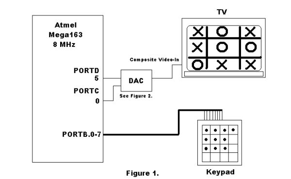
The goal of this project was to play a simple game outputted to a television via direct NTSC signal generation into a composite video input of a television. Obviously, the outputting of material to a television is the most challenging part of this project (and not one to be taken lightly). Much of the information needed to produce the NTSC signals were derived from http://www.efd.lth.se/%7Ee96rg/mc/video/rtvideo.html which is also linked off the course home page. After many arduous attempts, we were able to do a few simple things at first and eventually built up to having a nice screen buffer and character library for which many applications can be found above and beyond Tic-Tac-Toe.

Why do this project?
The project is worthwhile for no other reason, because it is a cool idea to be able to produce television images with an Atmel Mega163 micro controller. Mind you, neither one of us had any idea how TV signals were generated prior to this project. By attempting this project, we have learned a great deal about how video signals are generated. This is a concept that was completely foreign to either of us prior to this project. Prior to this semester, no one in this class had attempted it, and we are still the only group to attempt it solely with an Atmel Mega163 running the standard 8 MHz without external sync hardware.
NTSC Basics
A television image is draw by an electron beam. This electron beam draws horizontal lines on the screen. It does this in two fields, an odd and even field which are interlaced to derive the final picture. The video signal that a TV receives controls the placement of the beam. NTSC is the standard way to generate television images in the United States.
A NTSC signal is generated by having 3 pre-equalization horizontal sync pulses, 3 vertical sync pulses, and 14 more horizontal sync pulses. No picture information should be outputted at these times. So then there are 242 frames left to display information in the manner shown above. Composite video signals need the following voltage levels:
A simple digital-to-analog converter can be used to output the appropriate values, as shown on our schematics page. Our scope output on the upper right for instance would output two white pixels for that particular horizontal scan line where the two peaks are. The valleys are hsyncs.
For more detail: Tic-Tac-Toe on TV