PIN 1 LED SUPPLY VOLTAGE
PIN 2 LATCH DATA INPUT B
PIN 3 LATCH DATA INPUT A
PIN 4 LEFT DECIMAL POINT CATHODE
PIN 5 LATCH STROBE INPUT
PIN 6 OMITTED
PIN 7 COMMON GROUND
PIN 8 BLANKING INPUT
PIN 9 OMITTED
PIN 10 RIGHT DECIMAL POINT CATHODE
PIN 11 OMITTED
PIN 12 LATCH DATA INPUT D
PIN 13 LATCH DATA INPUT C
PIN 14 LOGIC SUPPLY VOLTAGE, Vc
How to program an AVR:
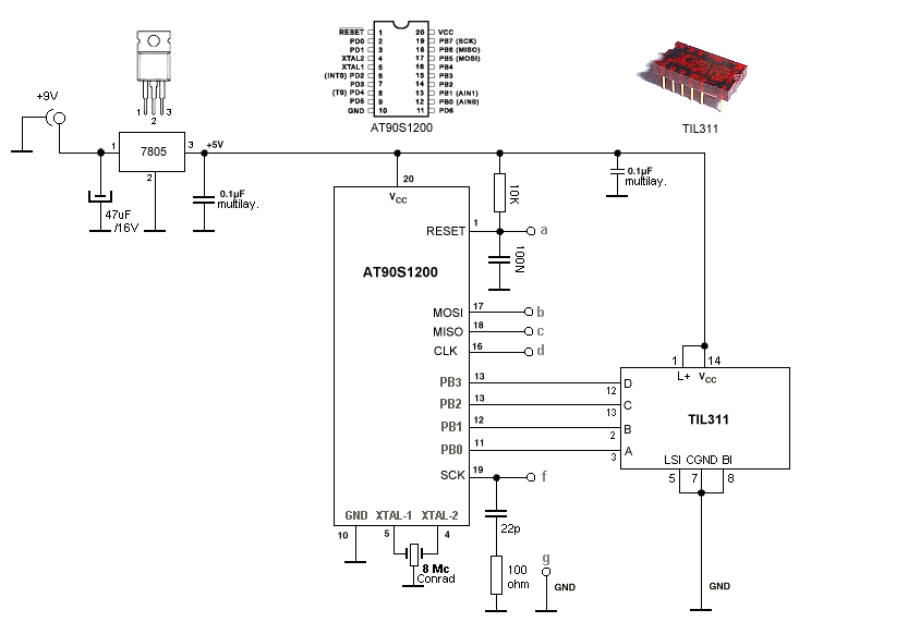
To control the TIL311 you must set a 4-bit number (16 values -> 6=hex, 10=deci) on the inputs. In this example use the first nibble (nibble is half a byte, 1 byte = 8-bit) of PortB of the AT90S1200. If you want to display e.g. the number 8 on the display, you must set the bit on input D of the TIL311, D has the binairy weight 8 (D=8, 1000 binairy):
ldi display, 0x08
out PORTB, display
With only a few lines of assembly you can wake-up the TIL311. The next example is a decimal upcounter with two TIL311’s.

Brief introduction:
On this page you will find a few examples on how to control a TIL311 hexadecimal dot-LED-display. The TIL311 was developed in 1972 by Texas Instruments, it’s a display with integral TTL logic, it has a 4-bit databus, so with only a few wires you’re able to display all hexadecimal numbers (0 – F), which means also all decimal numbers (0 – 9) With a microcontroller attached to it you can display various things, like temperature (e.g. 2 displays), make a counter, an electronic dice, etc. Here a diagram on how to connect a TIL311 to a microcontroller.
For more detail: TIL311 / INL0397-1 Hexadecimal Display usning AVR microcontroller
