Specifications
Input: AC, DC or AC+ DC to > 10 KHz
Ranges: 200 mv, 2V, 20V, 200V, 600V full scale
Accuracy: ±1%, depending on divider resistor selection
Crest Factor: 1 to 3, up to 5 with degraded accuracy
Input impedance: 1 Megohm shunted by 20 pf
Battery drain < 300 uA
Introduction
The DVMs in the photo above measures AC voltage by detecting the peak AC voltage on the 200 VAC or 500 VAC scale, then assumes that the input wave form is a sine wave and scales the meter reading to 0.707 of the peak. It is not useful for measuring waveforms that are not sinusoidal. When I found the AD737 at my favorite distributor for only 135 Thai Baht (Approx. US$4.40 today), I bought a couple, and only adding a few other components, made this adapter for my voltmeters.
The main differences between one of the application circuits in the AD737 data sheet are the addition of a MCP1702 micropower 3.3 volt regulator to split the power supply and two 11 volt zener diodes to prevent the voltage across the chip to become high enough to damage the chip in case the input is connected to an excessive voltage while in the 200 mv full scale setting.
The input divider was salvaged from an inexpensive DVM in which the mode selector switch wore out. The resistor values are all standard 1% values and even if the desired values are not available, you can get to within a percent by using series/parallel combinations of other 1% values.
The AC input coupling capacitors are two film capacitors rated for “X” usage (across the power lines), being rated at 300 volts each, the capacitors can safely handle an offset of over 800 volts DC, but the resistor divider probably can not, so I decided to limit use to under 600 volts DC.
The input impedance of 1 Megohm shunted by 20 pf was selected to match that of my Tektronix oscilloscope so that I can confidently use probes and other signal sources designed for sue with the scope. For this purpose, I added a BNC connector in parallel with the banana jacks at the input.
Construction
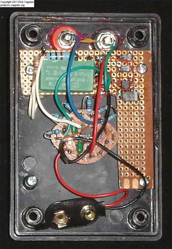
The circuit was made in two subassemblies. One is the resistor divider and the 3.3 volt power supply mouthed on the back of the two pole, six position rotary switch.
For more detail: TRUE RMS-TO-DC Adapter For DVM using microcontroller

