Introduction
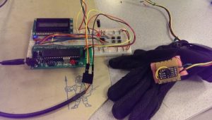
There are very few ways to improve one’s skills in conducting a live band. Practicing by conducting a real band requires coordination of many people and conducting along to pre-recorded songs does not provide feedback on the accuracy of the conductor’s selected tempo. The system we designed uses a glove with an accelerometer to track the user’s hand motions. With this information, we apply our heuristic algorithm to detect when each beat takes place. The system measures the timing between each beat and horizontal acceleration information to create real-time feedback for the conductor’s measured tempo and time signature. Furthermore, the system also plays pre-determined MIDI songs to provide real-time audio feedback to the user. With this feedback, the user will be able to refine their control over tempo and improve their conducting skills.
High Level Design
Rationale
Conducting a band is difficult. The conductor needs to pick the right tempo for the song to sound good. If the tempo is too slow, the song can drag on and the band can get tired because they hold out the notes for too long. If the tempo is too fast, the band may have difficulty in performing sections of the song which have complicated rhythms or fast runs of notes. Once the tempo for the song is selected, the conductor needs to maintain this speed for the duration of the song. It is common for songs to speed up over time, especially during high-energy segments of the song. Unfortunately, there are not many ways for an aspiring conductor to improve their skills. Perhaps the best way to do so is by actually conducting a live band. However, this option requires coordination among a large group of people and is not a very effective use of everyone’s time. Another option is to try conducting to a metronome or recorded music. Though this option may help the conductor gain an intuition behind what each tempo sounds like, there is no actual feedback behind how well the conductor is following these speeds. We chose to do this project to solve this problem. With our device, an aspiring conductor can get useful feedback on their skills on their own.
Logical Structure
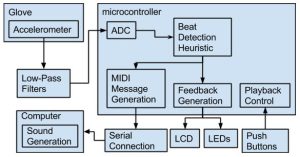
The logical structure of our project can be broken down into 3 categories: data input, processing, and output. Each of these categories is explained below and the block diagram in the figure below depicts the fully assembled system.
Data Input
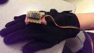
The user wears the glove, which has an accelerometer attached to it. The accelerometer outputs analog signals according to the x- and z-accelerations. These signals are low-passed to reduce noise. The low-passed signals are input to two separate ports of the microcontroller’s analog-to-decimal converter.
There are also 4 pushbuttons, each with their own function. These buttons provide the user interface with the device, allowing the user to re-calibrate the accelerometer, select the song to be played, and start and stop playback of the song.
Data Processing
The digital acceleration readings are used as inputs to the heuristic function we developed to extract beat detection musical statistics from acceleration values. The software detects when the beats occur and performs the necessary work to produce the visual and audio feedback signals.
Outputs
The software-calculated beats-per-minute reading and measured time signature are output from the microcontroller and displayed on an LCD. Furthermore, when a beat is detected, an LED is flashed to provide visual feedback to the user. The first 4 beats that are conducted after starting the playback of a song are special. The user provides 4 beats to provide the software with the appropriate tempo. This helps improve the accuracy and sound feedback for the first few beats of the song. These 4 beats have special LED indicators to notify the user when the song will start playing.
Upon each quarter of a beat, the microcontroller outputs serial messages indicating which notes should be turned on and which should be turned off. These serial messages are received by a computer which converts them into MIDI messages. These MIDI messages are then input into a music making program to produce the sounds.
Hardware and Software Tradeoffs
The accelerometer we chose outputs voltage values from 0 V to 3.3 V based on the magnitude of the acceleration detected. We chose an accelerometer that uses voltages instead of one that use SPI or I2C interfaces for a simpler software design, though possibly at the cost of better precision and noise. The accelerometer can operate measuring values in the range ±1.5g and ±6g. We chose the ±1.5g for better dynamic range and since hand motions are along that order of magnitude of acceleration. The reading tends to max out for larger hand motions but is sufficient for our purposes.
One way to connect the MCU to a MIDI player was to build a circuit that connects the MCU serial output to a female MIDI to USB connector for the player. This would essentially make the project a MIDI controller. However, we found an easier to interface with the player, which was to simply use a serial USB connector to a laptop. Hairless MIDI ⇔ Serial is free software that takes care of converting the serial messages into MIDI messages that can be played in real time. We later discovered there was some lag for the messages arrive and play on the laptop, so it’s possible there was a tradeoff between ease of use and speed of execution in making this decision.
Standards
The primary standard that is relevant to this project is the Musical Instrument Digital Interface (MIDI). The MIDI 1.0 standard allows electronic musical instruments and computers to communicate by sending instructions to each other. The instructions contain timing information and event information, which determine which sounds are played and with what intensity. MIDI is a serial communication protocol and while the hardware baud rate is 31.25 kBd, our setup sends serial messages via software at a rate of 38.4 kBd because computer serial ports can only communicate at multiples of 300 Bd.
The typical MIDI note message has 3 bytes: an action byte (for turning notes or off), a pitch byte (for the note to be played), and a velocity byte (for the volume of the note). Most of our messages look like the following (in hexadecimal notation):
90 3C 45
The 90 means play a note of the first channel (which is the only channel we use), the 3C denotes middle C, and the 45 means to play it at medium volume. To turn off that note, we issue the following command:
90 3C 00
Specifying 0 velocity effectively turns the note off.
Software
The software is governed using the Tiny Real Time kernel, which is a preemptive kernel that handles the multitasking that the project requires. There are three tasks that run in parallel in the program:
- beatSense, the meat of the program, which takes care of both the tempo calculation and the real time MIDI playback function
- buttonComm, which reads the button inputs and responds accordingly
- lcdComm, which prints outputs to the LCD every 100 ms
Tempo Calculation
The beats of the conducting pattern first need to be sensed in order to calculate the tempo of the user’s conduction. A three-axis accelerometer is used to measure the accelerations of the user’s hand movements. Of the three dimensions, only the x-axis and z-axis motions are needed. x-axis measurement accounts for left and right motions, while z-axis measurement accounts for the up and down motions.
The accelerometer outputs a 0 V to 3.3 V reading for the magnitude of the acceleration, which caps at ±1.5g for the mode that was used for this project. The x and z outputs are first low-passed to eliminate noise and then connected to Ports A0 and A1, the analog-to-digital converter of the MCU. Because only one input of the ADC can be sampled at a time, the x and z accelerations are captured on alternate iterations of the beatSense task.
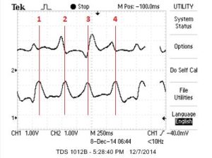
beatSense runs every 10 ms, which means a new x or z acceleration value is updated every 20 ms. This speed is more than enough for the slow hand motions that are to be measured. With the acceleration values, the beats of conduction can be detected. The waveform of a 4/4 measure of conduction is as follows:
The waveform of almost two 3/4 measures of conduction is as follows:
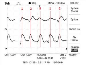
The top traces of each image are the x-acceleration output of the accelerometer and the bottom is the z-acceleration. As marked in the images, every beat results in a peak in the z-acceleration. Thus, beat detection is done by the detection of peaks in z-acceleration. To detect peaks, we save the history of a single measurement, that is, the current z-acceleration and the z-acceleration of 20 ms ago are used. Whenever a peak has occurred, the current z-acceleration must be lower than the previous one, which means a maximum had occurred in the previous iteration. Additionally the previous z-acceleration must be above a certain threshold for it to be counted a peak. In order to not count a peak multiple times, whenever a peak is a detected, a cooldown timer is started such that no peaks may occur in the next 100 ms. This is a reasonable assumption since no conduction should ever exceed 10 beats per second (or a tempo of 600 bpm).
While z-acceleration is used to detect beats, x-acceleration is used to detect time signature. When conducting 3/4 and 4/4, the second to last beat is always a motion to the right. This behavior also evident in the waveforms; the second to last beat results in a large increase in the x-acceleration. Whenever a beat is detected, we also check whether or not that beat is the second to last beat in a measure. This is done by calculating the difference between the current x-acceleration with the old, and checking if that value is greater than a threshold. The time between successive penultimate beats is used to determine the time signature. If it is found that penultimate beats occur every three beats, then the time signature is 3/4 and if they occur every four beats, the time signature is 4/4. The measurement of other time signatures is not supported.
The time between beats is determined with Timer2, which has a prescaler of 1024. Because the beat period is so long (on the order of hundreds of milliseconds) compared to CPU speed, a Timer2 overflow ISR is used to increment a counter in order to maintain a 16-bit timer. This counter is used to find the beat period and is zeroed subsequently. The actual tempo calculation is done by scaling the inverse of the beat period in lcdComm, so that it can be displayed on the LCD
MIDI Playback
The MIDI playback function of this project allows for the playing a song dynamically based on the tempo of the user’s conduction. These songs are hard coded as a 3D array in memory. The dimensions of the 3D array are the song length in number of beats, the number of sub-beats in a beat, and the number of notes that can be played at a time times two. The number of sub-beats in a beat is fixed at 4, which supports the playing of sixteenth notes, but no faster. The number of notes that can be played at a time is at 2, and our song structure only allows one note to played and one to be stopped (stopping a note is playing a note at 0 velocity) at the same time.
A sample song is shown below:
char song[2][4][4] =
{
//beat 1
{ {0x3e, note_on, 0x43, note_off},{0, 0, 0, 0},{0x40, note_on, 0x3e, note_off},{0, 0, 0, 0} },
//beat 2
{ {0x41, note_on, 0x40, note_off},{0, 0, 0, 0},{0x43, note_on, 0x41, note_off},{0, 0, 0, 0} }
}
The above song has a length of 2 beats and 4 sub-beats per beat. In beat 1, note 0x3e (D4) is played on the 1st sub-beat and on the 3rd sub-beat, note 0x40 (E4) is played and note 0x3e (D4) is stopped. In beat 2, note F4 is played and note D4 is stopped on the 1st sub-beat, and G4 is played and D4 is stopped on the 3rd sub-beat. As a whole, 4 eighth notes are played (D-E-F-G). If a sub-beat is filled with all 0s, then that means nothing is done on that sub-beat.
Whenever a note needs to played/stopped, the code parses a sub-beat and forms an appropriate MIDI message to send to the MIDI player. In our setup, the MIDI player is a laptop and the MIDI messages sent to the laptop using serial connection on the MCU by the function fwrite. The serial messages are interpreted using the software Hairless MIDI⇔Serial, which a tool that converts serial messages into a virtual MIDI output. We use another software, loopMIDI, to create a virtual MIDI port that connects to Hairless and the application used to play MIDI output, LMMS.
The software keeps track of where in the song it currently is by beat_idx and sub_beat_idx variables, which indicate which beat and sub-beat it’s currently on. Whenever a beat is detected, all the remaining sub-beats of the previous beat are first played (explained later). Afterwards, the beat index is incremented to indicate that it is on the next beat of the song. The first sub-beat of that beat is then played. The other three sub-beats need to be interpolated since they do not occur on the beat and are played by an ISR controlled by Timer0.
Using the currently measured beat period, the duration of a sixteenth note is determined. It is simply a quarter of the beat period since the beat period is a quarter note. Timer0 is set up similar to Timer2 except that it has a prescaler on 256 because of its dealing with a shorter timeframe. The Timer0 overflow ISR, in addition to incrementing a counter like the Timer2 ISR, also checks if the counter has exceeded the duration of a sixteenth note. If so, the sub-beat index is incremented, a sub-beat is played, and the counter is zeroed out. This process will continue until the all the sub-beats have been played. In the event that another beat is detected before all the sub-beats have finished playing, they are all immediately played as mentioned before and the entire process starts over. Due to the fact that our songs are fairly short, they are on repeat until playback is stopped, so the beat index will wrap around once the end of a song is reached.
User Interface
The user interface for the system is handled by buttonComm and lcdComm. There are four buttons that control the user interface: a calibrate button, a song selection button, a play button, and a stop button. The system starts in the song selection mode, and LCD displays messages accordingly. In this mode, the accelerometer can be calibrated by holding down the calibrate button. Calibration changes the threshold used for peak detection. The idea is to hold the glove still when calibrating to determine the 1g z-acceleration that gravity induces. The threshold is set at 15% higher than the 1g acceleration. Songs are scrolled through when pressing the song toggle button. Play button will start beat detection and song playing after four beats of silence. The beat indices will be appropriately reset to ensure the song starts at the beginning. The LCD displays the tempo of conduction as well as the time signature. The stop button will halt beat detection and send a MIDI message to turn off all notes. buttonComm executes every 10 ms, but has a later deadline as to not interfere with senseBeat. It checks for whether or not any button has been pushed and performs the appropriate actions if so.
The song toggling button needs to be debounced due to its toggling nature. This is done by a simple debouncing technique that keeps a 1-bit state variable for that button. When the button is pressed, the state is set to 1 and the button action will not occur unless the state transitions from 0 to 1 to avoid multiple triggers of the action upon the button press. Once the button is no longer pressed, the state resets to 0.
Hardware
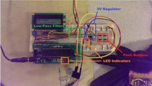
The principal component of our project is the accelerometer. We use a breakout board designed by Modern Devices which provides easy access to a Freescale MMA7361L accelerometer. The accelerometer is set to measure ±1.5g.
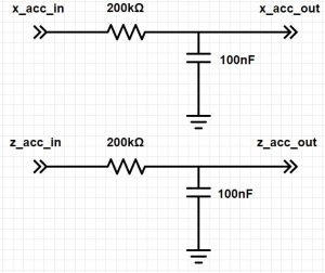
The z-acceleration and x-acceleration lines are then input to two identical low-pass filters. These filters had a resistance of 200 kΩ and capacitance of 100 nF. This allows for the desired acceleration signals on the order of 1-4 Hz to pass to the ADC inputs while filtering out the high-frequency noise from the accelerometer and environment.
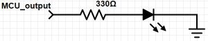
Two of the LEDs are connected to the appropriate output pins through a 330 Ω resistor. The third LED is internal to the course-provided prototype board and is connected to the microcontroller output through a 300 Ω resistor.
Similar to the LEDs, each of the 4 pushbuttons are connected to their appropriate input pins through a 330 Ω resistor. Each of these input pins have a pull-up resistor, so they read a logical high when the buttons are not pressed.
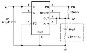
The accelerometer has an ideal input voltage of 3.3 V. However, we use the TPS7230QP 3 Volt regulator to power the accelerometer due to its availability in lab and minimal impact on performance. As seen in below, we use the manufacturer suggested circuit for this voltage regulator.
The LCD is connected to the microcontroller as described in Lab 1 of the ECE 4760 course website.
Results
Speed of Execution
We have tested the speed of our design to ensure that the user gets prompt, real-time feedback when conducting the virtual band. Since it is impossible to measure the exact time the user wants to indicate a beat with their hands, much of this speed testing was based on quality of interaction with the device. Specifically, we conducted the sample songs and focused on the timing of the blinking LED which indicates when a beat is detected. To the best of our perception abilities, we have found the LED to consistently blink on each blink.
It is also important for the audio feedback to be prompt in its response to the conductor’s beats so as to not throw the conductor off of his or her rhythm. We tested the device by conducting songs over a variety of tempos, including extremely slow (~60 bpm) and extremely fast (~200 bpm) speeds. For the slower speeds, the songs sound appropriately responsive to the conductor’s beats. However, at faster speeds, a small delay in the audio feedback becomes apparent. Looking into this issue, we discovered that it is not the microcontroller code that is causing this delay, since the serial-to-MIDI conversion program indicates the arrival of messages on time. The error must therefore lie within the commercial serial-to-MIDI or MIDI song playback software. The timing of the offbeats was also measured by ear. As the conductor increases the tempo, the offbeat notes also play at the appropriately faster speed.
Accuracy
The accuracy of the beats per minute calculation of the tempo was tested as seen below. Using a function generator, we supplied waves of known frequencies. The subsequent measurements showed the bpm readings to be within 5 bpm, thus satisfying our constraints.
| Input Freq(Hz) | Input Freq(bpm) | Avg.Measured Tempo(bpm) | Error(bpm) |
|---|---|---|---|
| 1.525 | 91.5 | 89 | 2.5 |
| 2.632 | 157.9 | 156.5 | 1.4 |
| 3.472 | 208.3 | 212 | 3.7 |
We have verified the functionality of the time signature detection by swapping time signatures while conducting a song and monitoring the displayed output. The system eventually converges on the correct time signature. However, it takes around 2-4 measures of conducting for the program to recognize the change in time signature. Future work in this project may be in improving the time signature detection algorithm to converge on the measured time signature faster.
The buttons were tested for responsiveness and accuracy. Throughout our interactions with the project, we have not encountered any unexpected or inaccurate behavior of the pushbuttons and have not seen any responsiveness issues.
Safety
Throughout the project we made careful considerations in design, development, and testing to create a safe product. We ensured that no electronics would come in direct contact with the user. Furthermore, foam padding has been added to the bottom of the accelerometer breakout board to prevent the soldered pins from irritating the user’s hand. Further precautions have been taken when actually using the device. We ensure the space around the user is cleared so they do not accidentally hit any equipment or another person while conducting the band.
Our project is very self-contained and has very little impact on its surrounding environment. Since the device uses wired communications, it does not run the risk of interfering with other projects’ wireless communications.
Usability
Our product should be usable by anyone who can properly fit the glove onto their right hand. If the user is vision or hearing impaired, he or she will be able to use the other of the two forms of feedback to improve their conducting skills. The user interface has been designed to be simple and require minimal knowledge of the device before using it.
Conclusions
Summary
In general our project has met our expectations. We were expecting to be able at minimum to be able to reliably detect the beats of conduction and be able to play some sort of simple music to that beat. The user can change his/her tempo of conduction at will and the speed of the playing music will adjust almost instantly.
The greatest drawback of our design is that music playback lag that is very noticeable when conducting at higher tempos. Because beat detection is very timely, this lag is likely due to the communication time from the MCU to the laptop , and could result from the fact that we are using software to handle the serial to MIDI conversion. Something that we could do differently next time is explore using hardware to support the MIDI conversion and connection. This could very well fix our lag problems at fairly little added complexity.
One feature we had hoped to have at the beginning of the project was the ability to load in MIDI files that could then be interpreted and played by our code. We had anticipated this feature would be time consuming to implement, but could be extension to our project. Another area to improve on is the detection of time signature, which currently works but can be a little finicky as it is fairly difficult to characterize based on the x-acceleration.
Our design does indeed conform to the MIDI standard since the notes in the songs are able to be transmitted and played in a MIDI player.
Intellectual Property Considerations
There are problems with intellectual property with our project. Almost all code written was done by ourselves or adapted from previous lab assignments in this class. The exception to this is the TRT kernel. We did not reverse engineer any design nor sign any non-disclosures to obtain any of our parts. We do not plan to patent or publish any of our work.
Ethical Considerations
We have followed the IEEE Code of Ethics to the best of our ability throughout working on this project. We were very aware of any actions that we took so as to ensure the safety and health of our peers. We constrained ourselves to one lab bench to prevent from interfering with the work of anyone else. The project was not particularly hardware intensive and the wiring that was required was done with care. All wires used for trimmed and the circuits were kept clean to minimize any damage they could cause. All sound outputs from the laptop are kept at a reasonable volume and should cause no discomfort anyone nearby. During testing, we plugged in a pair of earphones to keep from disturbing others in the lab.
The glove unit itself was designed to ensure the safety of the user. A piece of foam is used to cushion the space between the top of the glove and the accelerometer. This allows for more comfort and separates the user from the electronic components. Unfortunately our design is not completely fair to all users due to its nature as it requires the full use of a hand in order to use the glove and be able to conduct music. Lastly, we have done our best to assist others whenever necessary and credit others whenever their ideas are put to use.
Legal Considerations
The MIDI standard is an open communications standard that is free to use. All other software we used is free and easily obtainable from the internet. As far as we know, there are no other legal considerations to be aware of.