Background:
I used a Basys3 FPGA board however, this game can be created with the FPGA of your choosing.
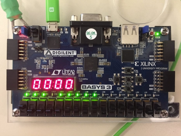
This is a straightforward and enjoyable game which uses the five push buttons to represent the “Whacks” and five LEDs to represent the “Moles.” Each push button corresponds to one of the LEDs/Moles and the only way to score is to press down on the push button when the corresponding LED is on. There will be no points deducted if you fail to press down on the push button when the LED is not on but, if you succeed in whacking a mole the 4 digit 7 segment display will display the score in real time. To make the game more interesting a random number generator will be implemented to create random patterns for the “Moles.” Lastly, three LEDs will be used to represent the time left on the game. Meaning, when all three LEDs go off, the game will over, and the score will be displayed in the 4 digit 7 segment display.
Step 1: Creating a Black Box of Game
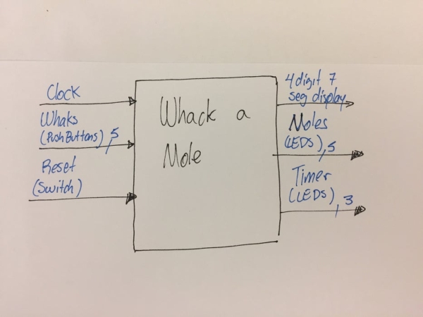
The first step, which comes before you start creating the code for the game is to create a black box of the overall functionality of the game. This should be as simple as possible but, must contain all of the inputs, outputs, and special fixtures that the game will have.
As you can see in the attached picture. There will be three inputs and 3 outputs, this step is important because it allows you to see the overall functionality of the game before you start creating the code.
Clock input: This will be the master clock that controls everything in the game. The Basys3 Board runs at 100MHz which is what I recommend to use for your master clock but, if you have a board with a faster clock I recommend you use that one instead.
Whacks (Push Buttons): This 5 bit input is self explanatory.
Restart: Just like in any game you need an on/off switch and a way for your game to restart itself when ever it is necessary. To make things easier use just one switch to have all of this functions. Meaning, whenever the switch is ON the gave restarts itself and it remains in an “off state” until the switch is brought to the OFF position which will start the count down time(one minute in this case) and start the game.
Four digit Seven Segment Display: Use the 4 digit 7 segment display to display the score in real time. Since the game only lasts one minute the 4 digits should be more then enough to display the score.
Moles (LEDs): To represent the “Moles” use five LEDs and assigned them with a corresponding push button once you write the code. A random number generator will be used so there should be enough patters and LEDs to make the game interesting.
Timer (More LEDs): Because we are already using the 4 digit 7 segment display you need to come up with a way to allow the user to know how much time is left before the game is over. This is not necessary but, it is a really nice feature to have. I recommend using 3 LEDs to represent the time, just like in the picture. Meaning that when ever the 3 LEDs are you gave about 1 minute left on the game. When the first LED goes off you have 30 seconds before the end of the game. When the second LED goes off you have 10 seconds and lastly, when all three LEDs go off the game is over. I personally prefer this method of representing the time because you never know with exactitude how much time is left on the game. Which brings more excitement and thrill to the game.
This is what I made my game to be but, I encourage you to change things up and maybe add a few more inputs & outputs. For example: maybe you could manage to add a speaker that plays a song or make noises whenever a mole has been whacked. You can add as many effects as you want which will make the game more enjoyable and heart racing when you play it. Just make sure that all the inputs & outputs are clearly defined in the BackBox Diagram.
Step 2: Creating Block Diagram of the Components of the Game
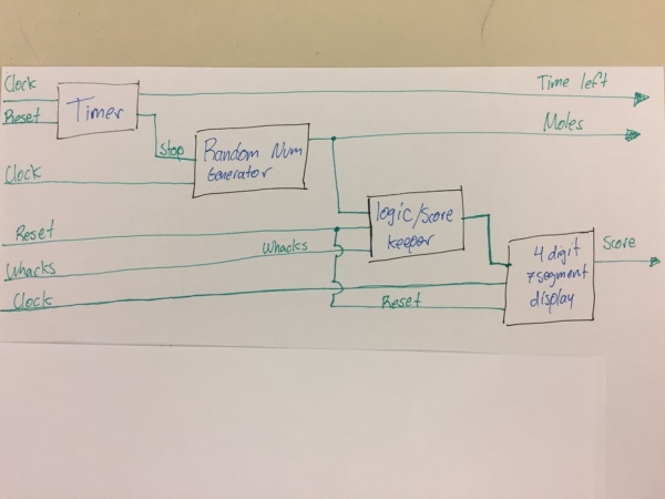
Proceeding from your Black Box diagram create a list of all the components that will come together to make your game work. Once you have a solid list of all the components create a more detailed Black Box Diagram that connects all the components that will work together. This step is important because it will allow you to break down your game into smaller and simpler parts.
As you can see I listed four main components. There are actually 3 clocks controlling the game however, every clock comes from the main 100MHz clock. So in a way you will be manipulating that clock to make slower clocks. To make the diagram a little simpler to follow and to be able to see the overall functionality clearer, I just put clock. But, you need to take keep in mind that you will be manipulating the main clock to create a set of slower clocks.
Timer: As you can see the timer has two inputs and two outputs. This timer will use the 100MHz clock, meaning when ever a variable counts to 100 million a seconds will have passed. If another variable counts 60 times 100 million then, a minute would have passed. Using this the Timer will output the LEDs that represent the time remaining. When the timer counts 60 times 100 million or the reset input is high then, the timer will output a signal that will make the Random Number Generator output nothing (zeros).
Random Number Generator: This component will also work with the 100MHz clock. You can not actually make a random number generator but, if you have something that is changing fast like the 100MHz clock, and manipulate it you can use that as a random number generator. Meaning, that the number is changing so fast and you are manipulating the number in such a way that it makes it unpredictable for humans to know what number will be generated. But, since the number is changing so fast you need to make a slower clock that only pulls out a random number when ever you need it. If you want to change the state of the “Moles” two times per second you need to make a slower clock that only updates the random number two times per second. Other wise the moles will be changing at a rate of 100MHz, which will be way to fast for the human eye to be able to keep up with. It will also have a “stop” input which when high it will make the generator output zeros.
Score Keeper: This component has three inputs. It will compare the push buttons state and the moles. If both of them are high then it will add one point to the score. Store that number, and send/output a signal to the seven segment display. When ever the reset is on high it will restart the score to zeros and send that signal to the seven segment display.
4 Digit 7 Segment Display: This component will also run with the 100MHz clock but, because of the way the seven segment display works you need to turn on/off the individual digits. If you do that 100MHz the human eye won’t be able to keep up and won’t be able to see the score. So you need to manipulate this 100MHz clock and slow it down to make a 60Hz clock. Which is slow and fast enough for the human eye to see a continuous number even if you are turning the individual digits on/off. This component will display the score that is inputed from the score keeper, and will reset to zero when ever the reset button is high.
If you added more component make sure to add this components in this block diagram. This is important because it will allow you to see how things are inter connected and will also help you understand how your game is structured. If you think is necessary you can even make a state machine that further explains the behavior your game will have once it is working correctly.
Step 3: Creating the Code
Once you have all the diagrams you need, have seen how things will be inter connected and have an idea of how your game will behave, you can begin coding. I am attaching the source codes which were written in VHDL. I also put comments in the code that will help you identify the components to make it easier to follow/read the code. If you followed the first two steps correctly you should be able to create a game in another language or FPGA like an Arduino.
I recommend you make each individual component work independently. Once you get the components to work you can put them together and make a big code that uses all the components. Using this method you will be able to tackle the game code in parts which will make it a lot easier to fix the problems that may occur.
I did not explain the code in detail. However, you can easily google how to make the different components and/or look at my code to try to understand how it all comes together. Good Luck creating the Project!
Step 4: Play the Game
Source: Whack-a-Mole Using a FPGA Board