Motivation:
I love astronomy and astrophotography very much. I am sure that like me, all amateur astronomers would want a inexpensive personal observatory for taking pictures of the fabulous universe.
Astrophotography, especially deep-sky photography, requires high precision in tracking (to counter the earth’s rotation) and focusing. A decent equatorial mount plus autoguider can take care of tracking while a motorized focuser can achieve high precision in focusing. They are all quite expensive! There isn’t really any reliable substitute for a good mount and autoguider but a motorized focuser is relatively easy to DIY at a very low price.
Also, It would be convenient to be able to control the mount remotely. I am from China and I am currently studying in US for college. It would be nice if my high school astronomy teacher can access my telescope remotely and show her class the real time images for planets or star clusters. There exists some solutions to control the telescope remotely but I am not satisfied with them.
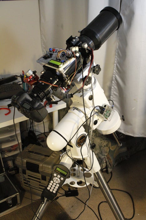
So, I started this proof of concept project that allows user to remotely control the equatorial mount, the focus of the telescope and the camera via a webpage.
Introduction:
You can watch the demo video above to see how the project works. The project consists of 4 parts
- Motorized focus control
- Micro-controller communicates with the mount with the synscan serial communication protocol
- Micro-controller communicates with other devices via a custom made serial JSON string protocol
- A webpage as an interface to control the mount, the focuser, and the camera
In this tutorial, I will lead you through the process of creating a focuser and running my code to control the telescope.
Step 1: Everything You Need
I made this project based on the equipment I have. If you have the same equipment I have, you can follow my exact steps, but if you don’t, you may need to tweak things or implement your own code to get it to work.

Tools:
- A set of Allen keys
- Caliper
- Hand drill
- Access to a 3D printer
- A CAD software (I used Fusion 360 student version)
Astronomy equipment you may already have:
- A telescope with a decent manual focuser (I have a sharpstar CF90-II)
- A sky-watcher equatorial mount with synscan v3 or v4 (I have an EQ6-pro with syscan v4)
- A canon DSLR (I have a 6D, Nikon does not work because gphoto2 cannot control Nikon in bulb mode)
Parts:
- Raspberry pi (for remote DSLR control, I have a rpi2)
- A wifi dongle for the raspberry pi (unless you have a rpi3)
- Teensy3.2 (communicate with the mount and other device)
- Long good quality usb micro cable * 2 (for powering rpi, and teensy)
- Long good quality usb mini cable (for your DSLR)
- RJ-11 jack and cable (connect teensy with syscan)
- Max232 chip (convert syscan’s RS-232 level to teensy’s ttl level)
- 10 uf capacitors * 4 (work with max232 chip)
- LCD screen 1602a
- 28YBJ-48 Stepper motor
- ULN2003 stepper motor driver board
- MXL 45 teeth timing belt pulley (replace the focuser knob)
- MXL 15 teeth timing belt pulley (attached to the stepper motor)
- Timing belt
- Buttons * 3 (control focuser)
- Potentiometer * 3 (change speed of stepper motor and adjust brightness/contrast of LCD)
- #6 screws and nuts (install 3D printed focuser)
- breadboard * 2
- Lots of jumper wires
- 5V2A power supply for the rpi, and 12V 2A power supply for the mount
Note:
- If you don’t have a DSLR, you can skip the parts related to it and build a mount controller.
- The value of the capacitors for max232 does not matter that much, I have seen several diagrams with different values. As long as it is not too small, you are fine. If you have a breakout board, that is even better.
- When you buy the timing belt pulley, make sure the bore diameter matches your focuser and stepper motor.
- Do not buy long opening timing belt and attempt to glue it into a circle. I have done that and I have tried everything but nothing works. I got mime from McMaster-Carr.
- A good quality usb cable can save you hours debugging weird issues.
- I used teensy3.2 micro-controller. It is an Arduino compatible but more powerful. Some of my code is Teensy specific (for example IntervalTimer). If you want to use the code on an Arduino, you need to make some modification.
Step 2: Design the Electronic Focuser
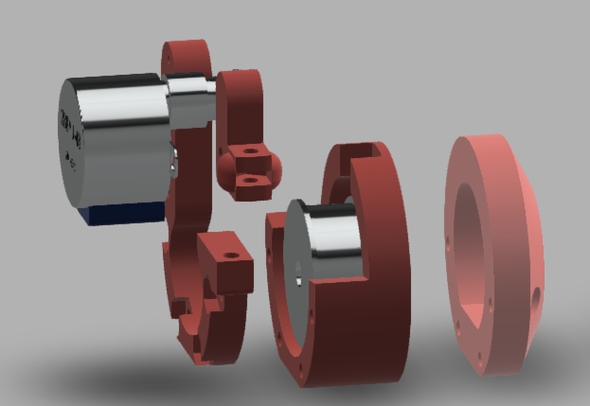
My design is partially inspired by this post. The general idea is to make a device that lets the motor turn the focus knob instead of hand. I chose to use stepper motor because it is very precise and my testing shows that with the timing belt mechanism to increase the torque, it is powerful enough to adjust the focus when using a DSLR. I used the timing belt mechanism because it offers an easy switch between manual focus control and motorized focus control by changing the tension in the belt. In my design the body of the electronic focuser consists of 3 pieces. A piece that attaches to the focuser of the telescope (inner), a piece that serves as a spacer (middle) , and a piece that holds the stepper motor (outer). All three pieces are connected together using four long #6 screws and nuts embedded in the outer piece. In addition, there is another piece that is used to adjust the tension in the belt. This separation makes 3D printing easier later and for different telescope, all you need to do is to design a different inner piece.
The stepper motor holder I designed is based on my telescope. Yours may have slightly different parameters. So it is always nice if you can CAD the whole thing and verify it works before printing.
Step 3: Print and Assemble the Electronic Focuser
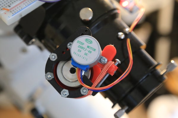
After you finish your design, you can 3D print the part and install it on your telescope. The installation is straight forward. Just follow the pictures and the CAD design (try the exploded view). The 1st image above shows the situation when the belt is tightened and the 2nd image shows when the belt is loose.
Here is a list of tips that may help you:
- In most cases you can use Allen key to take off the hand knob on the focuser. When you install the large timing belt pulley, make sure the screw goes into the little tab on the axis.
- Always pre-drill pilot holes before drilling the actual hole.
- You can wrap the tension adjust piece with rubber band so it auto retracts.
- For connecting the stepper motor and the outer piece, you can pre-drill a hole that is slightly smaller than the screw and thread the screw in for a tight connection.
Step 4: Driving the Stepper Motor
The stepper motor is connected to the driver board, which is connected to the teensy micro controller. If you are not familiar with stepper motor, this Wikipedia page and this link can be helpful. In writing the code to control the stepper motor. I referred to this link. I implemented 2 driving mode: two phase full step and half stepping. Two phase full step provides more torque but less precision, while half stepping provides twice the precision but less torque. The following array contains the state of the four stepper motor pins.
const static boolean cycle[8][4] = {{true,false,false,false},
                                    {true,true,false,false},
                                    {false,true,false,false},
                                    {false,true,true,false},
                                    {false,false,true,false},
                                    {false,false,true,true},
                                    {false,false,false,true},
                                    {true,false,false,true}};
In half stepping mode, the states of the 4 pins cycle through all 8 combinations in the array, but in two phase full stepping mode, the 4 pins cycles through index 1,3,5,7 of the array. Two push buttons control the direction of the motor by cycling through the array in different direction.
When using a particular driving mode the speed of a stepper motor depends on the interval between the states of the pins changes. Stepper motor requires very precise timing to drive, so I used a timer interrupt to drive the motor. The interrupt is triggered at a fixed interval. Every time an interrupt is triggered, the code sets the stepper motor pins to the next combination in the array. A potentiometer is used to change the interval of the interrupt, thus changing the speed of the stepper motor.
Please refer to step 5 for wiring and step 6 for the code
Side note: It is a bad idea to use a raspberry pi to drive stepper motor. The motor would misbehave under short step interval because a raspberry pi runs an OS and is hard to achieve hard real time control.
Step 5: Connect the Circuit
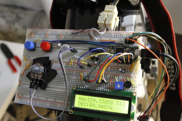
Connect the circuit board based on the diagram shown above. For the motor control mode wire and display setting wire, you can add switches to make it easier to use. For switches and potentiometers, you can also add additional capacitors to smooth the input if you want.
Reference:
Max232 chip: https://www.sparkfun.com/tutorials/215
LCD screen: https://www.arduino.cc/en/Tutorial/HelloWorld
syscan hand contrl serial port: http://www.skysafariastronomy.com/products/skyfi/i…
For the entire system to work, you also need to connect the teensy and the DSLR to the raspberry pi, connect the syscan hand control with the RJ11 jack, and power the rpi using a 2A power supply.
Step 6: Teensy Code
To compile this code, you need to install the aJSON library. Just download the zip here: https://github.com/interactive-matter/aJson . In the arduino IDE, Sketch -> Include Library -> Add .ZIP Library to add the library. Then, go to ~/Arduino/libraries/aJson-master and replace the aJSON.cpp file with my version (attached below). It addresses this issue.
This code controls the stepper motor, talk to syscan hand control using the syscan serial protocol and communicate with other device using serial JSON string protocol. It has a circular buffer that queues up outside request and execute commands in the buffer at a fixed time interval. Though, here I am connecting the teensy to a raspberry pi, but you can easily modify my code to make it talk to a wifi module or a bluetooth module if you don’t want the camera control part.
The serial JSON string protocol I implemented here is quite interesting. The device has an internal JSON like tree structure that has getters and setters for different properties. Below is what it looks like.
{focuser : {mode : 0, interval : 3000}, telescope : {EQ_Coord : {RA : 50.5, DEC :85.6}, tracking : 2, in_goto : 0, slew : "AU2"}}
Any subset of this JSON tree structure is a valid command, with empty object being get and non-empty values being set. For example, a command like {telescope:{EQ_Coord:{}}} means getting the current equatorial coordinate of the mount. The teensy would reply with the sub tree filled in, for example: {telescope:{EQ_Coord:{RA: 50.5, DEC: 85.5}}} . For goto a target, you can simply send {telescope:{EQ_Coord:{RA: 70.2, DEC: 40.8}}} and the teensy would interpret it as goto that coordinate. The parser is recursive so you can send {telescope:{}} to get all status about telescope, or do multiple get/set in one command. The code would also validate the input value in your set command and prompt you API error.
Aside from this project, If you want to achieve similar things, definitely take a look at my code.
Step 7: Raspberry Pi Code
Prepare your raspberry pi first. Configure your raspberry to connect to a wifi network or configure it as a soft access point. Also, it would be very convenient if you have configured VNC on your rpi, so you can remotely login to it. Please follow this tutorial: https://www.raspberrypi.org/documentation/remote-a…
The code that runs on the raspberry pi does the following things
- communicate with the teensy via usb serial and the JSON string protocol to control the mount and the focuser
- communicate with the DSLR using gphoto2
- hosts a webpage that displays a real time star map and provides an interface for controlling the mount, the focuser, and the camera
Here are the technologies involved:
- All the server-side script is written in Node.js,
- the webpage is written in angular.JS and d3.
- node-static is used to serve the static webpage.
- socket.io is used for client-server communication
- node-serialport is used for accessing the serial port
- The star map is inspired by VirtualSky
- The star data used is taken from the HYG database
I used a webpage as an interface because it works on all smart devices. Theoretical, any browser that supports HTML5 should be able to access the page and control everything.
Setting up the raspberrypi:
wget https://raw.githubusercontent.com/gonzalo/gphoto2... && chmod +x gphoto2-updater.sh && sudo ./gphoto2-updater.sh
curl -sL  https://deb.nodesource.com/setup_6.x  | sudo -E bash -
sudo apt-get install -y nodejs
install my code
cd ~
mkdir Projects
cd Projects
git clone  https://github.com/yhzhao343/wifi_TeleCtrl.git

cd ./wifi_TeleCtrl/mount_ctrl
npm install
cd public
mkdir image
To run the code do:
node ~/Projects/wifi_TeleCtrl/mount_ctrl/simple-server.js
You can also configure the pi to run it at startup
After the server is running, you can open a browser and go to the local IP address of your raspberry pi using port 8080. For example, in my case, my rpi’s local ip address is 192.168.0.15 . I can access the page by putting 192.168.0.15:8080 in my browser. You can login to your router or hover the mouse on the network icon in the raspberry pi to get its local IP address.
Source: Wifi-controlled Telescope+DSLR With Motorized Focuser