There are numerous posts on Instructables about how to make a flickering LED candle. This is my version.
The project requires the following components:
1. Tiny45 AVR Microcontroller (Tiny13 would also do)
2. 1W Warm white (or yellow) LED
3. Perspex tube
4. AA or AAA size batteries- 4 (alkaline or NiMH)
5. PCB stock (or a general purpose veroboard)
6. Battery holders
7. 1/4W resistors 50 Ohm- 4 and 10K -1.
8. On/Off switch
9. Connecting wire
10. piece of wood for the base
11. masking tape
Tools:
1. Solder iron and solder
2. Hot glue gun
3. AVR ISP Programmer
4. screwdriver, files, drilling machine and suitable drilling bits.
Step: 1 The circuit diagram
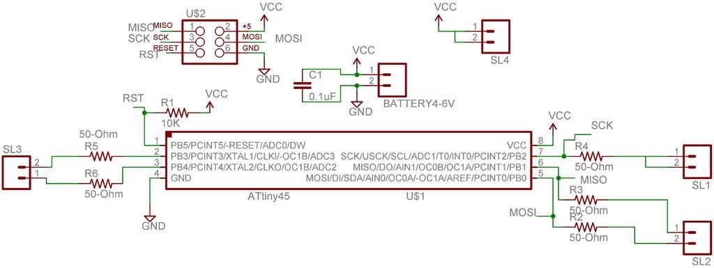
The required circuit diagram for the candle is here. Also seen is the board layout. In the board layout, the blue tracks are handled as jumper wires. The complete circuit is split in two boards, one containing the controller and the has the 1-W LED. The two boards are arranged in a double-decker, circular PCBs. The idea is to have a smaller total diameter for the circuit. four 2-pin connectors are used to connect the controller board to the LED board. The fifth connector on the controller board is for the power supply.
Step: 2 Making the PCBs
I used Modela Milling machineModela Milling machine to mill and cut my boards. You can get these boards fabricated from commercial PCB manufacturers such as PCB ExpressPCB Express or you can even make them at home as described herehere.
Step: 3 Soldering the PCBs
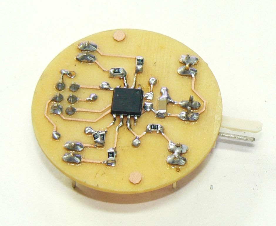
I soldered all the components as seen in the photographs. By distributing the circuit on two boards, one for the controller and another for the LED is not only useful in reducing the diameter of the board but also to ensure that when the controller board is programmed through the ISP connector (by first disconnecting the LED board from the controller board), the LED does not load the ISP signals.
I soldered all the SMD components first, followed by the jumper wires and then the rest of the components.


