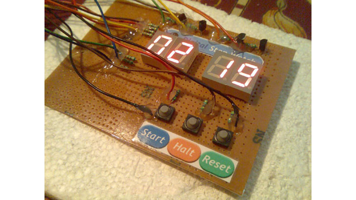
In this tutorial we will make a “Digital Stop Watch” using an AVR ATmega8 Microcontroller. This will help you learn many concepts like
- Multiplexed Seven Segment Display Interfacing
- Using AVR Timers
- Using Interrupts
- And many others too.
The code is written in C language for avr-gcc (WinAVR) .
Steps to Build the “Digital Stop Watch” using AVR ATmega8 MCU
- Make the circuit according to the schematic on general purpose PCB or a BreadBoard.
- Make a project in AVR Studio and add a new file to the project. Copy/paste the “c” code. Set optimization as “o2” and CPU frequency as 16000000Hz. Save and Build the project. You will get a HEX file.
- Burn this HEX file to an ATmega8 MCU using a tool such as eXtreme Burner AVR.
- Set High Fuse = C9(Hex) Low Fuse = FF(Hex). How to do this depends on you programmer software.
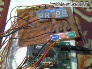
I have use a xBoard MINI development board for fast and easy prototyping. The Displays+Transistors+Key are on the Veroboard while the Core CPU unit + power supply is in the xBoard MINI. It can be programmed “In System” over USB Port using eXtreme Burner – AVR software toolkit.
How to Use the “Digital Stop Watch”
When initially powered up the Stop watch is in “STOP” condition. This is indicated by a blinking display. The count is 00:00 initially. Press “START” to start the watch. The blinking will now stop and the display will be fully on. It will start counting and MIN:SEC is displayed. The stop watch can be halted at any time by pressing “HALT” key. In halt state the counting freezes and the display starts blinking. You can press “START’ key again to resume counting from there. The “RESET” key is used to reset the clock to 00:00 i.e. 0 minute and 0 sec.
Digital Stop Watch Schematic

Digital Stop Watch C Source Code.
/*

Description:   An AVR ATmega8 based Digital Stop Watch

            Project.
________________________________________________________

Author:  Avinash Gupta
Date: 04 July 09
Web      www.eXtremeElectronics.co.in


*/

#include <avr/io.h>
#include <avr/interrupt.h>
#include <util/delay_basic.h>

#define true 1
#define false 0

#define SEVEN_SEGMENT_PORT PORTD

#define SEVEN_SEGMENT_DDR DDRD

volatile uint8_t digits[4];

//Global variable for the clock system
volatile unsigned int   clock_millisecond=0;
volatile unsigned char  clock_second=0;

volatile unsigned char  clock_minute=0;
volatile unsigned char  clock_hour=0;

//Display hiding system
uint8_t hide_display = false;

//Blinking system

uint8_t blink_display = true;


void SevenSegment(uint8_t n,uint8_t dp)
{
/*
This function writes a digits given by n to the display
the decimal point is displayed if dp=1

Note:
n must be less than 9

*/
   if(n<11)
   {
      switch (n)
      {
         case 0:
         SEVEN_SEGMENT_PORT=0b00000011;
         break;

         case 1:
         SEVEN_SEGMENT_PORT=0b10011111;
         break;

         case 2:
         SEVEN_SEGMENT_PORT=0b00100101;
         break;

         case 3:
         SEVEN_SEGMENT_PORT=0b00001101;
         break;

         case 4:
         SEVEN_SEGMENT_PORT=0b10011001;
         break;

         case 5:
         SEVEN_SEGMENT_PORT=0b01001001;
         break;

         case 6:
         SEVEN_SEGMENT_PORT=0b01000001;
         break;

         case 7:
         SEVEN_SEGMENT_PORT=0b00011111;
         break;

         case 8:
         SEVEN_SEGMENT_PORT=0b00000001;
         break;

         case 9:
         SEVEN_SEGMENT_PORT=0b00001001;
         break;

         case 10:
         //A BLANK DISPLAY

         SEVEN_SEGMENT_PORT=0b11111111;
         break;

      }
      if(dp)
      {
         //if decimal point should be displayed
         //make 0th bit Low
         SEVEN_SEGMENT_PORT&=0b11111110;
      }
   }
   else

   {
      //This symbol on display tells that n was greater than 10
      //so display can't handle it
      SEVEN_SEGMENT_PORT=0b11111101;
   }
}

void Wait()
{
   uint8_t i;
   for(i=0;i<10;i++)
   {
      _delay_loop_2(0);
   }
}


void Print(uint16_t num)
{
   /*

   This function breaks apart a given integer into separete digits
   and writes them to the display array i.e. digits[]

   */

   uint8_t i=0;
   uint8_t j;
   if(num>9999) return;


   while(num)
   {
      digits[i]=num%10;
      i++;

      num=num/10;
   }

   //Fill with leading 0s

   for(j=i;j<4;j++) digits[j]=0;
}


void main()
{
   uint16_t i;

   // Prescaler = FCPU/1024
   TCCR0|=(1<<CS02);

   //Enable Overflow Interrupt Enable

   TIMSK|=(1<<TOIE0);

   //Initialize Counter
   TCNT0=0;

   //Port c[3,2,1,0] as out put
   DDRC|=0b00001111;

   PORTC=0b00001110;

   //Port D

   SEVEN_SEGMENT_DDR=0XFF;

   //Turn off all segments
   SEVEN_SEGMENT_PORT=0XFF;

   //Set up the timer1 as described in the
      //tutorial
      //TCCR1B=(1<<WGM12)|(1<<CS11)|(1<<CS10);

   //initailly stop the timer by setting clock source =000
   TCCR1B&=(~((1<<CS12)|(1<<CS11)|(1<<CS10)));
      OCR1A=250;

      //Enable the Output Compare A interrupt
      TIMSK|=(1<<OCIE1A);

      //Enable interrupts globally

      sei();

      //Continuasly display the time
      while(1)
      {
         int disp;
      disp=(clock_hour*100)+clock_minute;
      //disp=(clock_minute*100)+clock_second;

      Print(disp);

      if(!(PINB & (1<<PB2)))
      {
         //RESET PRESSED
         clock_millisecond=0;
         clock_second=0;
         clock_minute=0;
         clock_hour=0;
      }

      if(!(PINB & (1<<PB1)))
      {
         //halt pressed

         //stop the timer
         TCCR1B&=(~((1<<CS12)|(1<<CS11)|(1<<CS10)));

         //Start blinking the display
         blink_display=true;
      }

      if(!(PINB & (1<<PB0)))
      {
         //start pressed

         //start the timer
         //Set up the timer1 as described in the
            //tutorial
            TCCR1B=(1<<WGM12)|(1<<CS11)|(1<<CS10);

         //Stop blinking the display

         blink_display=false;

         //Show the display
         hide_display=false;
      }

         _delay_loop_2(0);
      _delay_loop_2(0);

      }


}

ISR(TIMER0_OVF_vect)
{


   /*

   This interrup service routine (ISR)
   Updates the displays

   */
   static uint8_t i=0;

   if(i==3)
   {
      //If on last display then come

      //back to first.
      i=0;
   }
   else
   {
      //Goto Next display
      i++;
   }

   //Acivate a display according to i

   PORTC=~(1<<i);

   if(hide_display)
   {
      //Show a blank display
      SevenSegment(10,0);

   }
   else
   {
      //Write the digit[i] in the ith display.

      SevenSegment(digits[i],0);
   }

   //Handle blinking

   if(!blink_display) return;

   static uint8_t blink_counter=0;

   blink_counter++;
   if(blink_counter == 16)
   {
      blink_counter =0;

      hide_display=!hide_display;
   }

}


//The output compate interrupt handler
//We set up the timer in such a way that
//this ISR is called exactly at 1ms interval
ISR(TIMER1_COMPA_vect)
{
      clock_millisecond++;
      if(clock_millisecond==1000)
      {
      clock_second++;
         clock_millisecond=0;
         if(clock_second==60)
         {
            clock_minute++;
            clock_second=0;
         }
      if(clock_minute==60)
      {
         clock_hour++;
         clock_minute=0;
      }
      }
}
Downloads
- Schematic in PDF format.
- Schematic in GIF format.
- C Source Code
- HEX Code ready to burn
- AVR Studio Project as ZIP file
Project Video
Read more: Digital Stop Watch with ATmega8 using microcontroller