LC Meter:
Schematic Source code
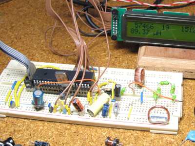
This is the project I am currently working on (2010-01-23). The LC meter is based on Elmcie or Elsie and other similar LC meters. This project is in a very early prototype stage and is at the moment only capable of measuring inductors. Even though I have build the first prototype on a breadboard the results are very impressive. No problems with instability of the LC oscillator. Seems to measure the inductance of a small wire in the nH range. Just for fun I connected a power transformer and I measured an inductance in the range of 7H for the primary winding.
I did some calculation based on the current consumption of the unloaded transformer and it seems to work out O.K. On the pictures I connected a big LCD (2×40) but that is just for debugging. The final meter will have a nice and small 1×16 display. The debug values on the top row of the display are: 57466: Accumulated value of Timer1. 19 is the amount of (20ms)interrupts it took to accumulate the Timer1 value. 151226 is the calculated frequency of the LC oscillator.
Just a little reminder to myself of what I want to make
- Maybe use multiple calibration L’s or C’s to make it more accurate in some ranges.
- Show negative values on te display to indicate the calibration is off.
- Normally connected to the network, maybe also on a 9V battery (backlight off).
- Extend it with frequency measurement, the 2nd half of the lm393 can be used as the input buffer.
- Use a multiplexer (74C151) to switch between multiple frontends for the LC meter.
- Mux can also be used to switch between a prescaler for the frequency measurement.
- show only significant digits for all measurement ranges.
- Use a bistable relay for switching between measuring L’s and C’s to save battery power.
- Built in Ni-MH battery charger? (7.2V GP Recyko?)
- Disable backlight when on battery power.
- Use a 3.5mm audio plug for connecting measuring cables.
- Other options for connecting cables: 4mm Banana / BNC / cinch / female 2p header.
- Put connectors parallel / select switch / change plugs.
- Use shielded microphone cable for measurement cables.
- Make some kind of pincet for measuring SMD components.
- Use 2x 1/2 ic socket for measuring components with small wire’s.
- Use 2 single row female header for measuring components with thicker wires.
- Make special connections for measuring SMD components (in different forms).
- Direct push buttons for selecting the right function (Frequency, Capacitors, Inductors)
- Maybe use a sliding switch for function selection.
- Rotary switch gives easily up to 12 different measurement functions.
- Also measure ACA / DCA / ACV / DCV / RMS / Averaging / Differential voltage / Resistors / diode test
- Pushing the frequency button multiple times selects beteween: Frequency / Period, Positive time, Negative time, dutycycle,
- Direct push button for zero calibration.
- Pressing the zero button shortly zero’s
- Last selected function is stored in EEPROM when turning the device off.
- All calibration values are stored in EEPROM and read upon power up.
- Add current source for diode / led test.
For more detail: LC Meter using AVR microcontroller

