
Summary of Transform a cheap RC Transmitter with Custom Firmware using ATMEGA64 Microcontroller
This article details how to reflash the Turnigy 9x RC transmitter with custom open-source firmware by modifying its ATMEGA64 microcontroller. It outlines disassembling the unit, creating a custom ISP cable from an IDE ribbon cable, and using an AVR programmer to install new software.
Parts used in the Turnigy 9x Custom Firmware Project:
- Turnigy 9x radio transmitter
- Old IDE cable
- Bits of wire
- 2x6 pin header (or cut connector piece)
- Solder
- Hot glue
- Soldering iron
- Hot glue gun
- Small saw
- Wire cutters/strippers
- AVR ICSP programmer (e.g., USBasp)
- PC
The Turnigy 9x is a cheap Chinese radio transmitter widely sold by hobby king and other retailers under a variety of names. This is a computerized radio transmitter and is already a great deal for the price ($53 currently) and pretty capable if you can figure out how to use the stock firmware. The microcontroller running the show is a common ATMEGA64 type and is not code protected. So several groups of dedicated hobbyists have completely rewritten their own firmware versions that vastly improve the radio and are open source to boot. This instructable will show the steps required to modify your radio and reflash it with the firmware of your choice.
Step 1: Tools and Materials
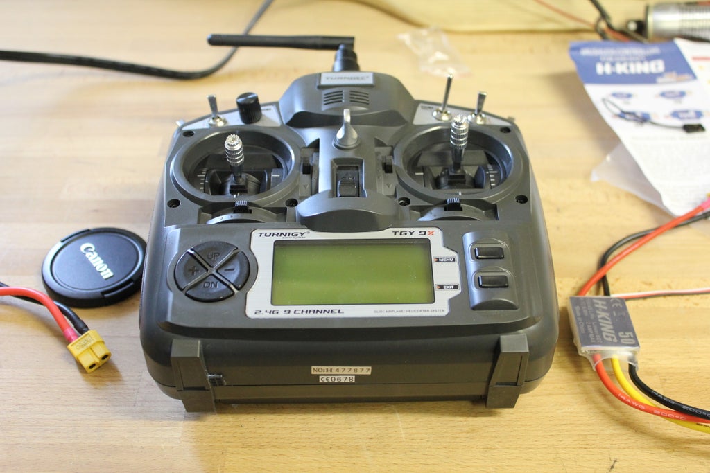
For this instructable I used:
an old IDE cable,
some other bits of wire,
2×6 pin header,
solder,
hot glue.
you will also need:
a soldering iron,
hot glue gun,
small saw,
wire cutters/strippers,
an AVR ICSP programmer, I used a USBasp
a PC.
Step 2: Open It Up!
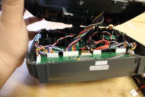
First thing to do is to remove the battery door and the battery pack within. Next unscrew the six screws on the back of the unit and gently lift the back of the case. Unplug the long connector in the middle holding the two halves together. Set the back half aside.
Time to tear apart your IDE cable. Remove six conductors from the ribbon on the side with the red stripe. These will be used to connect your programming port to the appropriate pads on the main board. Separate the wires and strip them. If you have a 2×3 female pin header plug you can use that, otherwise use a thin saw to cut a piece of the connector that is three long. carefully sand the edges smooth. take your mini-ribbon cable and bend every other wire the same direction, so that the wires line up with the plugs on the connector section. solder them together.
For more Detail: Transform a cheap RC Transmitter with Custom Firmware using ATMEGA64 Microcontroller
- What is the Turnigy 9x?
The Turnigy 9x is a cheap Chinese computerized radio transmitter widely sold by hobby king and other retailers. - Can I modify the stock firmware of the Turnigy 9x?
Yes, dedicated hobbyists have rewritten their own firmware versions that improve the radio, and this process involves reflashing the device. - What microcontroller runs the Turnigy 9x?
The microcontroller running the show is a common ATMEGA64 type which is not code protected. - How do I create the programming connection for the radio?
You can tear apart an old IDE cable, remove six conductors, strip them, and solder them to a 2x3 female pin header or cut connector section. - What tools are required to open the Turnigy 9x case?
You will need a small saw, wire cutters, strippers, and a screwdriver to remove the battery door, pack, and six back screws. - Does the Turnigy 9x come with custom firmware pre-installed?
No, it comes with stock firmware, but several groups have created open source firmware versions to vastly improve it. - What specific programmer was used in this guide?
The author used a USBasp AVR ICSP programmer for the modification process. - How should I prepare the wires from the IDE cable?
You must separate the wires, strip them, bend every other wire in the same direction to line up with plugs, and then solder them together.
