Summary of Running LED bicolor
This beginner-friendly project creates a running LED light using seven bicolor LEDs (red and yellow) controlled by an AT2313 microcontroller. The pattern is generated via assembler code written in Atmel's AVR Studio, utilizing Port B and Port D to reverse LED polarity for color changes. A 4MHz ceramic resonator serves as the clock source, and the circuit operates on 5V DC power.
Parts used in the Running LED Light:
- AT2313 Microcontroller
- Seven bicolor LEDs (Red and Yellow)
- 4MHz Ceramic Resonator
- Atmel AVR Studio Software
This is a good project for beginners. It is easy to build.This running LED light uses seven bicolor led’s red and yellow, they light up in a pattern that can be made within the program code.The program code is written in assembler. ATMELs AVR STUDIO is used to write the program.
The project uses the AT1200 but the AT2313 can also be used. As a clock source a 4Mhz ceramic resonator is used, this is cheaper than a crystal. The board has to be powered with 5V DC.
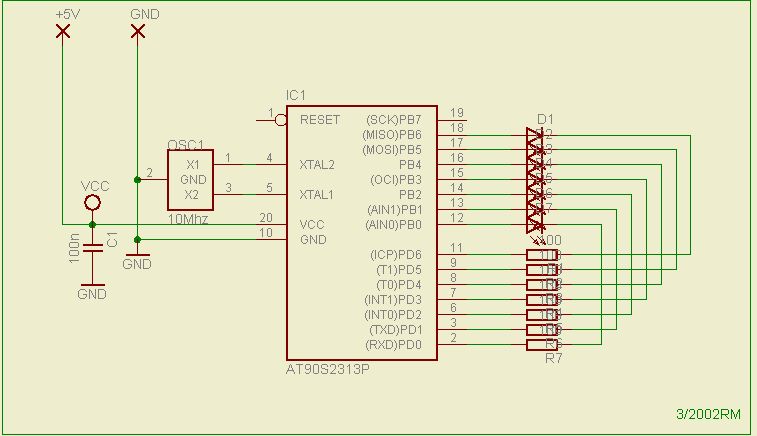
Because each I/O port of the AT2313 can draw 20mA current, each I/O port can drive a LED. The LED’s are connected to the port B and port D of the AT2313.

By connecting one end of the LED to port B and the other end of the LED the port D the polarity of the LED can be reversed. By putting a 1 on port B and a 0 on port D, the LED will go red. By putting a 0 on port B and a 1 on port D, the LED will go yellow. Now by writing sequently different bytes to the port B and port D, you can create different patterns in which the LED’s will light up.
For more detail: Running LED bicolor
- What software is used to write the program code?
Atmel AVR Studio is used to write the program code. - Can the AT1200 be used instead of the AT2313?
The project uses the AT2313 but the AT1200 can also be used. - How is the LED polarity reversed to change colors?
By connecting one end of the LED to port B and the other to port D, then setting specific high or low values on each port. - What voltage does the board require for power?
The board has to be powered with 5V DC. - Why is a ceramic resonator used instead of a crystal?
A 4MHz ceramic resonator is used because it is cheaper than a crystal. - How much current can each I/O port draw?
Each I/O port of the AT2313 can draw 20mA current. - Which ports are the LEDs connected to?
The LEDs are connected to the port B and port D of the AT2313. - What happens if you put a 1 on port B and a 0 on port D?
The LED will go red.