
Summary of Working with TWI (I2C) sensors / Devices
This article explains the Two Wire Interface (TWI), an I2C-compatible bus used by Atmel microcontrollers for serial communication at 100 kHz or 400 kHz. It details the master-slave communication protocol involving start bits, addresses, and acknowledge signals. The text highlights the ease of integrating modern hobbyist sensors like accelerometers and real-time clocks via TWI using libraries in Arduino or AVR Studio 6 with an ATmega8 microcontroller.
Parts used in the TWI Project:
- ATmega8 AVR Microcontroller
- AVR Studio 6 Software
- 24C32 I2C EEPROM
- GY26 I2C Digital Compass
- LIS302DL I2C Accelerometer
- DS1307 I2C Real-Time Clock
- PCF8574T I2C-to-Parallel Converter
- External Pull-up Resistors
Introduction
The I2C is a multimaster, multislave serial single-ended computer bus and was invented by Philips in 1982. The atmel microcontrollers use a compatible to I2C serial bus that is named TWI (Two Wire Interface). The TWI supports serial communication at 100 kHz and 400 kHz. The master and slave devices that are connected to TWI bus have a unique address from 0-127.
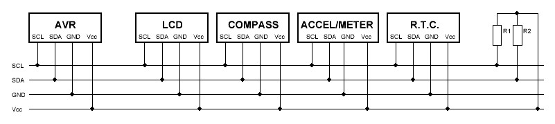
You can say: “The I2C bus is used since 1982. Why you choose now to write this article ?”. The answer is that the last years many new sensors and devices ideal for hobbyists such as accelerometers, LCD, digital compass, ultra sound range finders etc have designed to work on TWI bus because TWI needs only two external pull-up resistors and is very easy to be handle by microcotrollers. Moreover, many people have wrote libraries for supporting these TWI slave devices. A TWI slave device is very easy to be handled for example by Arduino. In our case we will work with AVR studio 6 and the classic ATmega8 AVR that works at 8 MHz internal RC oscillator. The TWI speed is 100 kHz.
How TWI (I2C) bus works
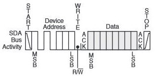
Master writes one byte to TWI slave device
The master device (AVR) calls the slave devices by sending a START bit. Then, it sends the 7-bit slave address (0-127) and follows the Read or Write bit (R/W). Because the master needs to write to the TWI bus the R/W bit is logic ‘0’. After that, the slave device respond to the master by an ACK bit (Acknowledge = logic LOW). The master sends the number of bytes wants to the slave but after every sent byte the master waits for ACK bit from the slave device. After the last byte the master will receive the last ACK and then it will send the STOP bit to end the comunication between the master and the current slave device.
TWI devices used in this project
-
24C32: I2C 32kbit eeprom (4 kBytes x 8 bit = 32 kBits). Slave address 0xA0.
-
GY26: I2C digital compass. Slave address 0xE0.
-
LIS302DL: I2C 3-axes I2C/SPI accelerometer Slave address 0x3A. This sensor works at 3.3V DC (Vcc).
- DS1307: I2C Real-Time-Clock. Slave address 0xD0.
-
PCF8574T: I2C-to-parallel converter. Usually used to drive dot matrix LCDs such as 16×2 or 20×4 characters. Slave address 0x4E. Some board designed to drive LCDs have different pin order from PCF8574T to LCD pins. Check your board version with an ohm meter.
For more detail: Working with TWI (I2C) sensors / Devices
-
What is the relationship between I2C and TWI?
TWI is a compatible version of the I2C serial bus invented by Philips, specifically used by Atmel microcontrollers. -
How many external pull-up resistors does the TWI bus require?
The TWI bus needs only two external pull-up resistors to function. -
What are the supported communication speeds for the TWI bus?
The TWI bus supports serial communication at 100 kHz and 400 kHz. -
How does the master device initiate communication with a slave?
The master sends a START bit followed by the 7-bit slave address and a Read or Write bit. -
What signal indicates that a slave device has successfully received data?
The slave device responds with an ACK bit, which is logic LOW. -
Which microcontroller and software are used in this specific project example?
The project uses the classic ATmega8 AVR working at 8 MHz internal RC oscillator with AVR Studio 6.
