
Summary of 50,000V High Voltage Power Supply
This article describes a DIY high-voltage power supply capable of generating approximately 50kV, emphasizing safety and the use of salvaged components to keep costs low. The project utilizes a flyback transformer driven by a 555 timer circuit, with voltage control achieved by adjusting frequency rather than PWM.
Parts used in the High Voltage Power Supply:
- Transformer
- Bridge rectifier
- Ceramic capacitors
- Flyback transformer
- MOSFETs (IRF540N or IRFP260)
- 555 timer
- 7812 Voltage regulator
- Perforated PCB board
- Resistors (10k, 10R, 680R, 470R)
- Potentiometers (10k and 100k)
- Diodes (1N4148)
- Transistors (2N2222, 2N2907, BC547)
- Infrared sensor and LED
- Banana female connectors
- Heatsinks
- Switch and pushbutton
- Shrink tube
- Variac (optional for adjustment)
DISCLAIMER:
- This is an extremely dangerous project, and it should only be attempted by people with experience in electronics, and specifically, High Voltage. If it’s your first time seek help for your own safety.
- Homemade High Voltage supplies are unlikely to meet any international standards, the safety and correct operation is NOT guaranteed at all, and will depend on the skill level of the builder, the effort put into it and most importantly, the common sense.
- This is not intended to be a tutorial on how to build a high voltage PSU, I only intend to show how I built it. This PSU has been built according to my criteria, and it can be useful if you’re looking for inspiration, but I discourage anybody who wants to replicate it blindly without applying his/her own common sense. I’m not an expert on the subject.
- I’m not responsible for any damage or injuries caused by the use of this information.
- Please, be extremely careful with High Voltage.
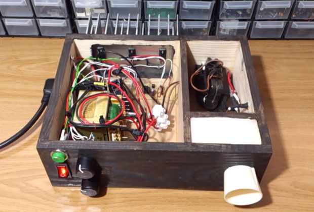
This high voltage power supply has been designed to output a fixed voltage of around 50kV, it could easily be converted to an adjustable supply by connecting a variac in case of using transformers or by adding some extra circuitry to regulate the power going in. I initially thought about a high frequency PWM to regulate the power going into the capacitors, but I abandoned the idea. I found that adjusting the frequency is enough to make the voltage vary by a significant amount, allowing some control over it, this happens because the flyback must operate at a certain frequency in order to maximize the output.
The total cost of building it is around 10 to 15€ since most of the parts (transformer, bridge rectifier, heatsink, flyback, switch, connector, cables…) have been salvaged, the only parts that I bought are the components of the 555 driver, the connectors and the capacitors. This shows the importance of having a big pile of electronic junk, specially old stuff with chunky electric and electronic components, it doesn’t matters if you have to pick it from the dumpster, it can save you tons of money on the long run and by repurposing these devices you’re being Eco-friendly. A good practice it to save the tin when desoldering and avoid throwing it into the trashcan and when you’re done with the board or there are no more valuable components you can take it to a place where it can be recycled properly.
Caution has been taken in order to isolate the high voltage output from the user and the internal circuitry.
The total cost of building it is around 10 to 15€ since most of the parts (transformer, bridge rectifier, heatsink, flyback, switch, connector, cables…) have been salvaged, the only parts that I bought are the components of the 555 driver, the connectors and the capacitors. This shows the importance of having a big pile of electronic junk, specially old stuff with chunky electric and electronic components, it doesn’t matters if you have to pick it from the dumpster, it can save you tons of money on the long run and by repurposing these devices you’re being Eco-friendly. A good practice it to save the tin when desoldering and avoid throwing it into the trashcan and when you’re done with the board or there are no more valuable components you can take it to a place where it can be recycled properly.
Caution has been taken in order to isolate the high voltage output from the user and the internal circuitry.
Step 2: Materials:
Power input:
- Transformer + bridge rectifier + capacitors
or
- Switching PSU
Both must be rated rated 5 amps and 20 volts at least for higher voltages.
- Separate* input for the driver
- Switch of choice and connector
- Shrink tube
Driver circuit:
- Perforated board of PCB to be etched
- 555 timer
- 8pin socket
- 7812 (if the power intput to the 555 is > than 14.5 or lower than 35)
- Small heatsink for the 7812 or other regulator (if needed)
- 2*100nF
- 1*1uF
- 1*10nF
- 1*68uF (or 100uF if you wish)
- 2*4148 diodes
- 3*10k
- (1 per MOSFET) 10R
- 1*680R
- 1*470R
- 1*10k pot
- 1*100k pot
- 2* pot knobs
- 1*2N2222 and 2N2907 (or other NPN – PNP pair)
- 1*Infrared sensor
- 1*Infrared LED
- 1*BC547 (or similar e.g: 2N2222 or 2N3904)
- 2*Banana female connector (or isolated high voltage connector)
- MOSFETS (I used 3* IRF540N but I recommend 1* IRFP260)
- Heatsink for the mosfets (and fan if needed)
- Pushbutton
For more detail: 50,000V High Voltage Power Supply
-
What is the output voltage of this power supply?
The supply is designed to output a fixed voltage of around 50kV. -
How can the voltage be adjusted?
Adjusting the frequency allows significant variation in output voltage without needing complex PWM regulation. -
What is the estimated cost to build this project?
The total cost is around 10 to 15 euros if most parts are salvaged from old electronics. -
Which MOSFETs are recommended for this build?
The author used three IRF540N but recommends using one IRFP260 instead. -
What are the minimum requirements for the power input?
The power input must be rated at least 5 amps and 20 volts. -
Is it safe to replicate this project without experience?
No, it is extremely dangerous and should only be attempted by people with experience in high voltage electronics. -
What method was abandoned for regulating power?
The author initially considered high frequency PWM but abandoned it because adjusting frequency was sufficient. -
How does the design ensure user safety?
Caution has been taken to isolate the high voltage output from the user and the internal circuitry.
