Summary of Using Maxim DS1307 Real Time Clock with Atmel AVR Microcontroller Using Atmega32
Building a digital clock using the Maxim DS1307 RTC and an Atmel AVR ATMega168 integrates timekeeping, calendar, temperature display, and UART setup. The project uses I2C to read time/date, a 2×16 HD44780 LCD for display, ADC for temperature, and UART to configure via HyperTerminal, demonstrating many AVR peripherals and tools like WinAVR and AVR Studio.
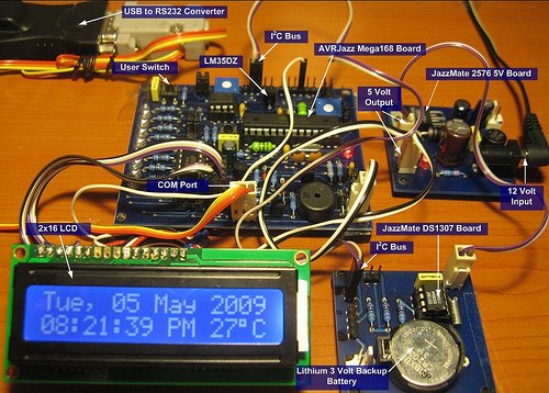
Parts used in the Digital Clock Project:
- AVRJazz Mega168 board (AVR ATmega168 microcontroller)
- JazzMate DS1307 Real Time Clock board
- JazzMate 2576 5 volt switching power board
- 2×16 LCD (Hitachi HD44780U)
- 10K trimpot
- TIP120 Darlington transistor
- 4K7 resistor
- WinAVR (GNU C compiler)
- Atmel AVR Studio 4
- STK500 programmer / AVRJazz STK500 v2.0 bootloader
Building our own digital clock is one of the dreamed project by most of the hobbyist or anyone that want to learn or involve seriously in the embedded system world; the ability to integrate time, day and date to the embedded system is one of the important knowledge that should be known by any embedded system designer. Today’s technology makes life easier as all these capabilities has already built nicely inside the Maxim (Dallas) DS1307 Real Time Clock (RTC) chip. The DS1307 is capable to count accurately the second, minute, hour, day of the week, date of the month, month and year include the leap year until the year 2100; with its I2C (read as I squared C, Inter-Integrated Circuit) interface capabilities make this chip easily to be integrated with widely available microcontroller that has build in I2C peripheral such as Atmel AVR Mega families or Microchip PIC18 families microcontrollers.
In this project we will learn to use the Maxim DS1307 RTC and Atmel AVR ATMega168 microcontroller to build quite sophisticated digital clock that have these following features:
- Using 2×16 LCD (Hitachi HD44780U) to display the digital clock
- Displaying days of week, day of month, month and year
- Displaying hour (24 or 12 hour format), minute and second
- Displaying current room’s temperature in centigrade format
- Setup the clock using the UART (Universal Asynchronous Receive Transmit) to communicate with the Windows’s HyperTerminal application.
In order to achieve this goal we will use many of the AVR ATMega168 peripherals; this makes this digital clock project is a good learning tools to explore and use many of the ATMega168 microcontroller sophisticated peripherals at the same time. I would suggest you could read my previous blogs to understand the basic of how to use the LCD, ADC, PWM, I2C and UART Atmel AVR peripherals, before you continue with this tutorial:
- Using 2×16 LCD: AVR LCD Thermometer Using ADC and PWM Project
- UART Communication: Working with AVR microcontroller Communication Port Project
- I2C or TWI (Two Wire Interface): How to use I2C-bus on the Atmel AVR Microcontroller
The following is the list of hardware and software used in this project:
- AVRJazz Mega168 board from ermicro which base on the AVR ATmega168 microcontroller (board schema).
- JazzMate DS1307 Real Time Clock board from ermicro
- JazzMate 2576 5 volt switching power board from ermicro
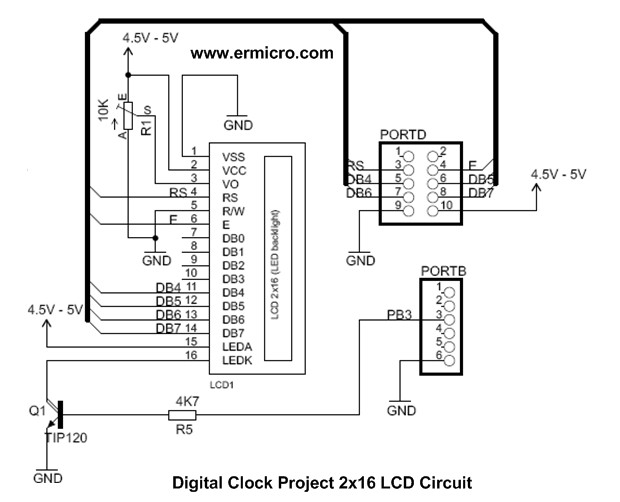
- LCD hardware: one 2×16 LCD (Hitachi HD44780U), one 10K trimport, one TIP120 darlington transistor and one 4K7 resistor
- WinAVR for the GNU’s C compiler
- Atmel AVR Studio 4 for the coding and debugging environment.
- STK500 programmer from AVR Studio 4, using the AVRJazz Mega168 board STK500 v2.0 bootloader facility.
For more detail: Using Maxim DS1307 Real Time Clock with Atmel AVR Microcontroller Using Atmega32
- What RTC chip is used in the project?
The Maxim (Dallas) DS1307 Real Time Clock chip is used. - What microcontroller board is used for the project?
The AVRJazz Mega168 board based on the AVR ATmega168 microcontroller is used. - How is the time and date communicated between the RTC and microcontroller?
Communication uses the I2C (Two Wire Interface) bus built into the DS1307 and AVR. - What display is used to show time, date, and temperature?
A 2×16 LCD based on the Hitachi HD44780U is used for display. - How is the clock configured from a PC?
The clock is set up via UART communication with Windows HyperTerminal. - How is room temperature displayed?
The project displays current room temperature in centigrade using the AVR ADC. - What software tools are used for coding and compiling?
Atmel AVR Studio 4 is used for coding and debugging and WinAVR provides the GNU C compiler. - What power supply board is used?
The JazzMate 2576 5 volt switching power board from ermicro is used. - Are additional discrete components required for the LCD?
Yes: a 10K trimpot, a TIP120 Darlington transistor, and a 4K7 resistor are used with the LCD.