
Summary of 2 Bit u Stepper using microcontroller
This article describes a custom-built stepper motor driver circuit designed to replace an overheating predecessor. The project utilizes an L298 driver IC and a microcontroller to implement 2-bit micro-stepping with PWM current limiting, ensuring smooth operation for bipolar motors while remaining cost-effective compared to commercial alternatives.
Parts used in the 2 Bit u Stepper:
- L298 (2Ampere) driver IC
- Microcontroller
- 2 simple DA converters
- Comparator
- 0.47 Ohm resistors
- 7474 flip-flops
- Bipolar stepper motor
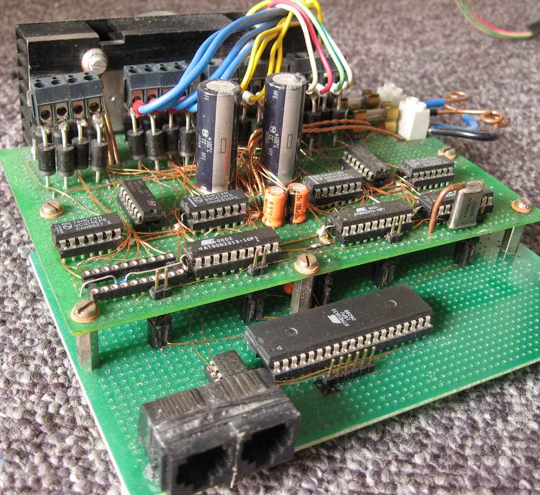
This is the second stepper motor driver circuit I build. The first one had 4 linear current sources and got so hot it was barely usable. It had some cool leds though. When I was searching for a better schematic on the internet I couldn’t find any to my linking. I did find some commercial micro steppers but they were all prohibitively expensive and had lots of electronics on a circuit board. Time to design my own. The result is the picture on the right which is from the Millproject and on the top board are 4 stepper motor circuitss
The main characteristics of this stepper are:
- Controls a bipolar motor.
- Uses the well known L298 (2Ampere) driver IC.
- PWM to limit power consumption.
- Microcontroller controlled, Easy to add more bits or other functions.
- Uses 2-bit micro stepping.
- Has step and direction inputs.
The hardware.
The microcontroller has 2 simple DA converters. One for each motor winding. Note that these DA converters are not linear. They are not supposed to be. To control a stepper motor with the smoothest speed, the input to the phases should be 2 sine waves with a 90 degree phase difference. The output of the DA converters goes into the input of a comparator. The comparator compares this reference voltage with the motor current. (Voltage over the 0.47 Ohm resistors). If the current reaches the limit a flip-flop is reset (7474), which turns of the L298 drivers. The 2 flip-flops are set at a steady rate by the microcontroller to turn the motor current back on. The width of the PWM pulses is determined by the self induction of the motor coils and the load of the motor.
The software.
At initialization the smallest interrupt routine I ever wrote is set up to trigger at a regular interval. This interrupt just generates a 1 instruction wide pulse to set the flip-flops and turn the motor current on. The main loop is almost as simple. It waits for a rising edge on the step input.
For more detail: 2 Bit u Stepper using microcontroller
-
What is the main characteristic of this stepper motor driver?
It controls a bipolar motor using the L298 driver IC with PWM to limit power consumption. -
How does the hardware limit the motor current?
A comparator compares reference voltage with the motor current across 0.47 Ohm resistors to reset a flip-flop when the limit is reached. -
Can this design add more functions easily?
Yes, it is microcontroller controlled and easy to add more bits or other functions. -
What type of input signals does the circuit use?
The circuit has step and direction inputs. -
Does the software use interrupts?
Yes, the smallest interrupt routine is set up to trigger at a regular interval to generate pulses that turn the motor current on. -
How are the DA converters described in the text?
The DA converters are not linear and are intended to output sine waves with a 90 degree phase difference for smooth speed control.
