
Summary of A 1.5 Volt, 1970’s Style LED Flashing Red Caboose Marker Light using tiny microcontroller
This article describes a circuit designed to simulate a 1970s incandescent caboose marker light using a red LED powered by a single 1.5V battery. The project utilizes an oscillator and driver block, a blink rate oscillator, and a power modulator to create a fade-in/fade-out effect rather than an instantaneous flash. By adjusting resistor values, users can customize the flashing duty cycle and luminance ramp rates to mimic real-world lighting behavior.
Parts used in the 1.5 Volt LED Flashing Red Caboose Marker Light:
- Red LED
- 1.5 volt battery
- Resistors (for selecting duty cycle and drive current)
- Capacitor (for voltage boosting)
- Transistor Q1
- Transistor Q2
- Bistable multivibrator circuit components
- Single sided surface mount printed circuit board
- Jumper
A circuit that drives a red LED from a 1.5 volt battery and simulates an incandescent light.
Duty cycle can be changed by selecting resistor values.
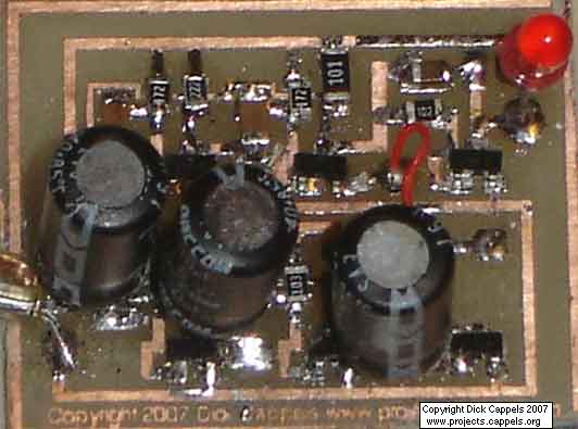
Photo 1. This printed circuit board is 3 cm long. The first prototype was made with through hole parts.
This is a single sided surface mount board with one jumper.
Overview
It started with email from mrpiggs. Mrpiggs is a model railroad artesian and is a direct contributor to this web page. Mrpiggs needed a circuit that would flash an LED, but nothing he was able to find quite fit his needs. The LED was going to be mounted inside a very small model caboose, and had to be battery powered. The lower the voltage, the easier it would be to fit the batteries into the caboose along with the flasher circuit. The venerable LM3909 LED flasher came to mind, but when it flashed, the LED only emitted a tiny blink, nothing the sustained flash on a real 1970’s style caboose marker light.
He needed a circuit that would provide a longer flash. And while we are at it, how about making the luminance of the LED quickly fade up and then quickly fade down similar to the appearance of the real thing. Incandescent lamps take many milliseconds to reach full luminance and even longer to die down, while LEDs switch on and off virtually instantaneously, giving a distinctly different visual experience.
Or, Even Better, see this demonstration on Youtube by clicking on the image or link below.
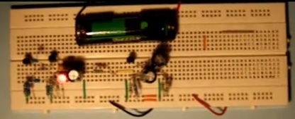
The resulting circuit can be customized to flash the LED at a wide range of rates, keeping the LED over a wide range of duty cycles. In addition, it can be made to allow the luminance to increase and decrease faster or more slowly as needed, and the drive current to the LED can be decreased to obtain the desired luminance. Click on Movie 1 to see what the blinking of the LED looks like with the circuit values shown in the schematic in figure 1.
The circuit can be thought of as being made from three major blocks: an LED Power Supply Oscillator/Driver, a Blink Rate Oscillator, and a Power Modulator to modulate the drive power to the LED, thus blinking it on and off. The discussion of the LED Power Supply Oscillator / Driver assumes that the LED is “on” -that is the signal from the Blink Rate Oscillator is always high, and this is modeled in the circuits in the description of the LED Power Supply Oscillator / Driver by showing the emitter of Q2 grounded.
The Led Power Supply Oscillator / Driver shown in Figure 2 is a pretty good little 1.5 volt LED power supply. An oscillator, a bistable multivibrator made of Q1 and Q2 oscillates at about 15 kHz with approximately a 50% duty cycle. There are many explanations of multivibrators on the web, so I will not discuss it here, except to say that the main weakness of this kind of oscillator is that if it ever stops, it needs to be “kicked” back into oscillation. A suitable “kick” can be made by disconnecting and reconnecting the battery. Don’t worry, its unlikely that the oscillators will stop spontaneously. If your oscillator ever stops while power is applies, it will most likely be the result of an intermittent connection of a temporary short circuit. These oscillators are very reliable.
The collector of Q2 drives a low value resistor so this stage it can supply enough current to drive the LED. The only problem here, is that the pulses coming from the collector of Q2 are about 1.4 volts peak-to-peak, and a red LED needs close to 2 volts to operate. The trick that gets around the problem is to alternately charge a capacitor to 1.5 volts, then place it in series with the 1.5 volt battery and and LED, so the LED can get up to 3 volts.
For more detail: A 1.5 Volt, 1970’s Style LED Flashing Red Caboose Marker Light using tiny microcontroller
-
How does this circuit simulate an incandescent light?
The circuit modulates drive power to make the LED luminance increase and decrease slowly, mimicking the slow rise and fall of real incandescent lamps. -
Can the flashing rate be changed?
Yes, the duty cycle and flashing rate can be customized by selecting specific resistor values. -
What voltage is required for the red LED to operate?
A red LED needs close to 2 volts to operate, which the circuit achieves by placing a charged capacitor in series with the 1.5 volt battery. -
What is the oscillation frequency of the driver stage?
The bistable multivibrator made of Q1 and Q2 oscillates at about 15 kHz. -
How is the circuit powered?
The circuit is powered by a single 1.5 volt battery. -
What happens if the oscillator stops working?
If the oscillator stops, it must be kicked back into oscillation by disconnecting and reconnecting the battery. -
What are the three major blocks of this circuit?
The circuit consists of an LED Power Supply Oscillator/Driver, a Blink Rate Oscillator, and a Power Modulator.
