
Summary of A credit card sized Ethernet Arduino compatable controller board using ATmega168 microcontroller
This article details the construction of a credit-card-sized, Arduino-compatible Ethernet controller board designed to replace expensive commercial shields. The project utilizes an ATmega168 microcontroller and includes embedded Ethernet capabilities, voltage regulators, and expandable I/O headers for sensors like thermometers and humidity monitors. A key feature is a DIP switch allowing automatic IP address selection without code modification. The guide covers schematic analysis, PCB fabrication via toner transfer, surface mount soldering techniques, and firmware programming using an FTDI-TTL cable.
Parts used in the Credit Card Sized Ethernet Controller:
- ATmega168 microcontroller
- Ethernet controller chip
- 74HC08 surface mount IC
- Voltage regulators (for +5v and +3.3v)
- 4 position DIP switch
- Ferrite bead
- Surface mount capacitors
- Resistors
- IC sockets
- LEDs
- Connectors (Ethernet jack and I/O headers)
- FTDI-TTL cable
I love the Arduino as a simple and accessible controller platform for many varied projects. A few months ago, a purchased an Ethernet shield for my Arduino controller to work on some projects with a mate of mine – it was a massive hit – for the first time, I could control my projects remotely using simple software.
That got me thinking – The Arduino costs about $30AUD, and the Ethernet board cost about $30AUD as well. That is a lot of money – Could I make a simple, dedicated remote controller for much cheaper? Why Yes I could. Could I make it the size of a credit card? Why Yes – I could!!
This project is my simple Arduino compatible controller that has embedded Ethernet, and the capacity to drive some extra I/O lines for projects, such as a Remote thermometer, a Remotely accessible Fridge controller, and a Remote Humidity sensor. I have to say from the start that I didn’t write all of the software, my mate Mikal did that – but this instructable is about making your own controller board!
Lets start!
Step 1 Here is the Schematic Diagram
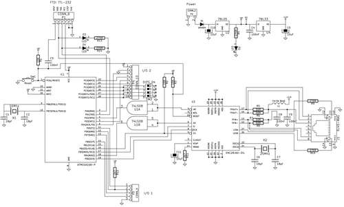 For the curious, this is the schematic diagram of my simple Ethernet board.
As you can see, there are a number of exposed header connectors that can be used to connect peripheral devices to.
The board is powered with a supply of between 7 and 12v. It contains voltage regulators to provide +5v and +3.3v for the Ethernet controller.
There is also a 4 position DIP switch that can be used to allow programmed functions to be modified. A failing of the standard Arduino Ethernet library is that the IP address for the board has to be set in code. Using the DIP switch, a block of addresses can be selected from as required. You can make 16 boards, and have each board automatically select a different address based on the switch setting. This is *really* handy when you have deployed 10 sensors around the house. All you need to do is set a switch and then they are configured.
The pinouts of the I/O connectors are;
I/O1 – 1 – PD5 (Arduino Pin 5)
I/O1 – 2 – PD6 (Arduino Pin 6 +pullup to +5v) – Used to connect a DS1820 Temperature sensor.
I/O1 – 3 – PD7 (Arduino Pin 7)
I/O1 – 4 – PD8 (Arduino Pin 8)
I/O1 – 5 – GND
I/O2 – 1 – +5v
I/O2 – 2 – GND
I/O2 – 3 – PD4 (Arduino Pin 4)
I/O2 – 4 – PC0 (Arduino Analog 0)
I/O2 – 5 – PD3 (Arduino Pin 5)
I/O2 – 6 – PC1 (Arduino Analog 1)
I/O2 – 7 – PC2 (Arduino Analog 2)
I/O2 – 8 – PC3 (Arduino Analog 3)
I/O2 – 9 – PC4 (Arduino Analog 4)
I/O2 – 10 – PC5 (Arduino Analog 5)
Step 2 The PCB Layout
Here is the PCB layout.
As with all of my projects, I make the circuit boards using press-n-peel blue as a toner transfer, and cuperic chloride as the etchant.
This layout can be printed onto a laser printer directly and used as artwork.
I wrote detailed instructions in my Arduino Wordclock writeup that you can follow to etch your own board. Check out http://www.instructables.com/id/The-Word-Clock-Arduino-version/step2/The-hardware-Make-the-controller-board/ for details.
One thing with this layout – I had to use a surface mount IC (a 74HC08) – Please do not be too scared by the surface mount technology – it is extremely simple to solder – as we will see in the next step.
Anyway – Go on – make a PCB, and check out the next step for how to assemble the board.
Remember – download the PDF file as the master – not the PNG picture – the PNG is just there so that you can see what it will look like – it is almost certainly not to scale! If you print the PDF full size (without scaling) then it is the exact correct size for Toner Transfer.
*Upate* – I just made another controller and realised that the pin spacing on the Ethernet jack was slightly off…. It has been fixed in the attached PDF layout.
Step 3 Soldering the Components
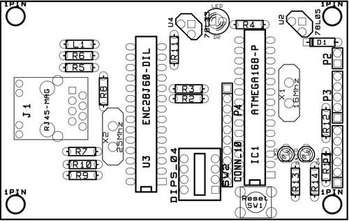 Now that we have a PCB, it is time to solder the components onto the board.
Download the attached top and bottom pictures of the board to let you know where the various parts are placed.
Also download the file to let you know where the 3 jumpers have to be installed on the top side of the PCB.
Lets start by getting the surface mount 74HC08 onto the board. I promise that it is not as hard as it looks.
Firstly – clean your work surface – there is nothing more frustrating that working in a mound of junk, when you have to do something carefully.
Continue by tinning the pads where the IC will be mounted – just apply a little bit of solder, not a great mound. Once the pads of the PCB have been tinned, get the part, place it onto the tinned pads, double check it is oriented correctly – The PCB has a dot where pin 1 should be – make sure that the part is facing that direction.
Then using a fine tipped soldering iron, touch one pad on a corner of the chip to heat it. Let the solder melt, and then let it cool. Look closely at the part to verify that it is still oriented correctly, and aligned with all the pads. Then solder the opposite corner.
Now, under a decent light, using a magnifying lamp, spend a minute double checking that the device is sitting correctly on the pads – if it isn’t, just re-heat a pin, and fix it up.
Once you are happy that the alignment is correct, heat the rest of the pads to melt the solder and connect the device. If necessary, add just a tiny bit of solder. Again – double check that your work is neat and clean – If you end up shorting pins together, don’t panic – just use a little bit of Solder Wick to remove the excess solder.
Once you have the 74HC08 soldered, pat yourself on the back, and go and show your fine work to a significant person in your life!! – You did it! You can now solder Surface Mount parts! A whole new world awaits you!
Next solder down the surface mount capacitors on the back of the board – they are *simple*, just use a similar process to what youhave already used – and do not be afraid to add a little bit of solder to keep the joints neat.
Next, turn the board over and install the jumpers on the top side.
Continue assembly by mounting all of the resistors, capacitors, the ferrite bead, IC sockets, LEDs and connectors.
Finish off by plugging the Micro controller into the socket, and the Ethernet controller into its socket.
Finally – spend a couple of minutes under a strong light double checking your work – If I had a dollar for every stupid time I forgot to solder a pin, and spent a night debugging something silly – I would be able to spend the rest of my life writing Instructables projects…. Sadly….. Anyway, where was I? Ahhh.
There – You have done it – you now own your first Ethernet micro board!
Now we just have to load up some software.
Step 4 Programming the Firmware
Now – we can load up the firmware.
Attached is a sample project – in this case, it is the trivial web server example from the Arduino library – it uses a DS1820 chip connected to Pin 2 of I/O 1.
I have to say that I did not write the web temperature project – it is the sample one from the Ethernet library – It works beautifully on this board!
Use a FTDI-TTL cable to download the code – you can get one of the cables from http://evilmadscience.com/partsmenu/130-usbttl They only cost $20, and I can guarantee that every project you make in the future will have that magic 6 pin interface….
For more Detail: A credit card sized Ethernet Arduino compatable controller board using ATmega168 microcontroller
-
How can I select different IP addresses for multiple boards?
You can use the 4-position DIP switch to select from a block of addresses, allowing up to 16 boards to automatically choose different addresses based on the switch setting. -
What is the power supply requirement for this board?
The board is powered with a supply voltage between 7 and 12 volts. -
How do I install the surface mount 74HC08 IC?
Tin the pads, place the part aligned with the dot marking pin 1, solder two opposite corners first to fix alignment, then solder the remaining pins. -
What software tool is needed to load the firmware?
An FTDI-TTL cable is required to download the code onto the board. -
Can this board drive external sensors?
Yes, it has exposed header connectors to drive peripherals such as a DS1820 temperature sensor or other I/O lines. -
How should I print the PCB layout artwork?
Print the PDF file full size without scaling to ensure the exact correct size for toner transfer. -
What chemical is used to etch the circuit board?
Cuperic chloride is used as the etchant after transferring the toner from a laser printer.
