Introduction
Navigation in the past has primarily relied on the use of a map, compass or other devices that must be interpreted visually. This project demonstrates the ability to navigate a user based on synthesized directional audio which allows the user to move to a known location without the use of a visual aid. The module uses a GPS, a digital compass, and an ATmega32 to generate sound based on the direction that the user must turn in order to face the correct direction.
Sound Byte
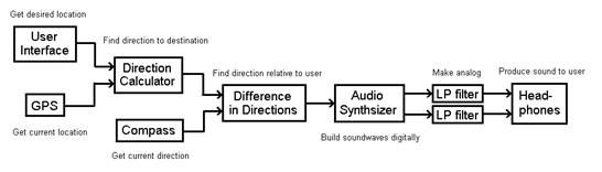
The goal of this project was to create a device that allows a user to navigate to a predefined location though the use of auditory guidance.
The module uses GPS and a digital compass to determine at what angle the user hears the sound pulses. On initial startup the user selects from a number of predefined locations through the use of an LCD screen. Once the GPS has a lock, the module determines the bearing (angle from true North) that the user must travel to get to the destination. This angle is compared with the compass output and a sound is made based on which direction the user must turn to face the final location. The sound consists of short pulses that are delayed between the right and left side and modulated in amplitude to give the effect of direction.
One example implementation of this is self guided tours. A user could be guided though a predetermined course by following the sound of a recorded person’s voice. In such a setting, if the user were to veer off course, the system would guide then guide the user back on course. Also, the direction of the guide’s voice could be used to highlight the object of interest along the tour.
The project idea came after Dr. Land mentioned that you could create the effect of a sound coming from a location by properly spacing the left and right channel by a certain distance. It seemed like a good idea to use this for navigation. This principle is based in the way that humans naturally hear perceive direction. Sound will reach each ear at a slightly different time and volume. Based on those differences, humans are able to determine the direction of sound in the horizontal plane.
The GPS communication uses a standard format (NMEA0283 V 2.2). These standards include GGA, GSV, GSA, and RMC. Of these, RMC (Recommended Minimum Navigation Information) is used in the final product for simplicity. Useful information from this protocol includes time, status, latitude, longitude, speed, and date. The other standards were used for development and debugging.
At this time there is no knowledge of existing patents, copyrights, and or trademarks that are relevant to this project. There are many devices that utilize GPS or a compass, but not together with this synthesized audio.
Program/hardware design
Having three group members made it nice as there were three distinct portions to the project, GPS, compass, and the synthesized audio. Each portion was developed on its own while keeping the others in mind and brought together at the end. For example, planning for the project included allocating resources between the sub functions including timers, registers, and ports.
Bringing together the three separate parts was tricky because of the timing budget. It was known that the GPS could only refresh at 1 Hz, but the sound and compass must be run much faster. We wanted the sound direction to change smoothly during the course of turning your head (faster than 1 Hz). Therefore, the GPS was allowed to run as fast as it could, depending on how many satellites were locked, and how many sound and compass functions were packed in between. This became tricky when multiple satellites were locked and the data stream from the GPS is continuous.
Compass
The digital compass module used was a Hitachi HM55B from Parallax, mainly because we already had it before the project. The communication between this device was done with three wires (clock, data, and enable) in an SPI like fashion. The communication is based on the Basic Stamp function SHIFTIN/SHIFTOUT which is a two wire communication. The challenge was to implement this in C for the ATmega32. Timer1 was used to control the timing of the function and three GPIOs were used for the three controls. The compare interrupt was used to generate the clock and data as this allowed for the clock time to be set at fine resolution resulting in the fastest possible operation of the compass. The clock signal was generated at twice the data rate so that data could be clocked on both the rising and falling edge of the clock in attempt to keep this function as general as possible in case of future use for other projects. To get data, the ATmega32 pulses the enable bit high for two clock cycles, then sends 0b0000 on the shared data_in and data_out line. After another enable toggle, 0b1000 gets sent to the compass signifying a start measurement command. The ATmega32 then sends 0b1100 and reads in four bits waiting for the data conversion to be done. When the compass sends back 0b1100, the data is ready. The ATmega32 then clocks in 22 bits (11 for x value, and 11 for y value) of 2s complement data MSB first. After properly formatting the data to get the proper sign an atan(x/-y) is called to result in an angle. This is then converted from radian to degrees and compensated for the difference between true and magnetic North (subtracting 12 degrees here in Ithaca). The whole function takes 60mS to run, which was determined to be fast enough.
Audio
The PWMs from timers 0 and 2 are used to generate sound pulses. Each timer is set to operate in fast PWM mode with a prescaler of one, giving the PWMs a sample rate of 62500 sample/second. The overflow interrupts of each timer are used to update the OCR.
Initially, timer1 of the Atmega644 was used to generate two PWM waveforms. The idea was that since timer1 has two output compare registers, it should be able to generate two PWMs. Timer1 was able to generate two PWMs, but since OCR1A was used as the top value and the PWM waveforms were not unique, the outputs of OCR1A and OCR1B toggled whenever the overflow interrupt was triggered. Using two timers prevented the overflow interrupt from toggling both pulses and also allowed for one timer to be used as a time based when an interrupt was triggered.
The code used for direct digital synthesis was adopted from lab2 written by Dr. Land4. The DDS process consists of a sin function quantized into a 256 entry table and a ramp table to linearly increase or decrease wave amplitude. For this project, two more tables were used to represent the phase offset and amplitude of the wave at a given source degree. These tables are precomputed to prevent extra computation during execution.
The premise of delaying sounds arriving at each ear to simulate sound localization is based upon interaural time difference. By delaying the sound arriving at one ear by up to 660 microseconds, the sound will have the appearance of coming from the side of the leading sound pulse.5 For example, if the channel going to the left ear is delayed, then the listener will interpret the delay as a sound source that is closer to the person’s right ear.
The phase offset table is used to represent the delay that is present at each degree. It was constructed to achieve no offset at a zero degree heading (the source is directly in front of the user) and maximum offset at 90 or 270 degrees. If the sound source is behind the user, then the channel of the ear furthest from the source will be fully delayed, encouraging the user to turn his or her head to better discriminate the location of the sound.
To make the sound direction more apparent, the amplitude of the delayed channel is also reduced. The sound is scaled according to a normal distribution so that full intensity is delivered when the user faces the source with a zero degree difference. As the user rotates away from the source direction, the amplitude of the PWM wave channel furthest from the source is reduced while the closer channel maintains full intensity.
GPS Communication
We used interrupt driven serial communication over the USART to receive data from the GPS. The GPS outputs NMEA sentences approximately once a second at 4800 baud. An example of one packet of NMEA sentences is shown below.
$GPGGA,144739,4251.9960,N,07806.0827,W,1,04,5.6,1898.0,M,34.5,M,,*61
$GPRMC,144739,A,4251.9960,N,07806.0827,W,1908.5,270.0,050510,5,E,A*2F
$GPGSV,8,1,32,01,12,205,-18,02,43,251,14,03,08,022,-22,04,05,271,00*75
$GPGSV,8,2,32,05,78,032,45,06,83,236,48,07,81,084,47,08,64,206,33*71
$GPGSV,8,3,32,09,90,086,52,10,42,202,13,11,26,284,-4,12,88,117,51*6C
$GPGSV,8,4,32,13,90,027,52,14,68,030,37,15,78,143,44,16,60,220,30*7E
There are several cases of redundant data between NMEA sentences and, for the purposes of this project; we only need one set of longitude and latitude. We decided to only read in the RMC (Recommended Minimum Content) sentence as a string and then extract the longitude and latitude from that string.
We use the USART character-ready interrupt which triggers as soon as a full character is received by the USART buffer. Once a character is ready in the USART buffer, the ISR writes the character to a string buffer and enters the state machine. The state machine successively checks for the characters that are expected to be seen at the beginning of the RMC sentence. If the program does not receive the expected header characters, it returns to the beginning of the state machine. If the input characters are ‘$’,’G’,’P’,’R’,’M’, and ’C’ in succession, program records the rest of the sentence as data. The sentence is terminated with the ‘\n’ character.
The data from the RMC sentence is written to a string buffer. Knowing the format of the RMC sentence, we use sscanf to extract the longitude and latitude. The longitude and latitude are sent in the format DDMM.MMMM where DD is in degrees and MM.MMMM is in seconds. We parse the data and recalculate the values in terms of degrees. It should also be noted that when writing to the string buffer, we ignored decimal points due to difficulties with sscanf reading in floating point numbers on the microcontroller. In order to compensate for this, we scaled the longitude and latitudes appropriately during the conversion into degrees and then radians.
Parts List:
White board $6.00
Mega32 $1
LCD (16×2) $8
9 volt battery $2
GPS module $25
Compass $0 (previously owned)
resistors $0
op Amp $0
total $42.00
For more detail: Auditory navigator Using Atmega644