Abstract
-A Roomba for boards
For our ECE 4760 final project we created a board climbing robot capable of cleaning the board autonomously. The robot uses neodymium magnets to stick to the board and moves across it with two continuous servo motors. It has bumper sensors on all four sides and keeps track of its orientation with two 1-axis accelerometers. The bot sweeps the board row by row starting from the top left corner. The bot can start at any point on the board and reposition itself to the starting point.
High Level Design
Rationale
We wanted a project that was not only impressive and innovative but also something practical. The board cleaning bot came as something in our desire to create a usable product. One of our members first considered the idea of an automated board cleaner while in a classroom years ago. What he first noticed was that during long lectures, professors had to pause to erase the boards every time the boards were full. It would be much more efficient time wise to have a bot do the erasing on a board while the professor lectures on another. Other applications are for college classrooms with exceptionally tall boards that are hard to reach. As far as we have researched, we could not find any reference about a board cleaning bot online. Our TA has even suggested that we patent this idea if it hasn’t already been.
Logical Structure
The design process for the bot was primarily focused on the hardware and chassis for the bot. For our proof-of-concept, we wanted something simple and flexible to work with. Since we had no idea of how we could get our bot sticking to the board and moving, we had no choice but to use legos to construct the chassis. Not only was the legos free, it also allowed us to easily make changes to the chassis.
The first stage of our work was to put together a chassis that can stick without sliding. We modeled our bot with Parallax’s boebot since it is the simplest to deal with. We attached two wheels to move and rotate the bot and made the chassis contain space to hold a standard board eraser. We also made sure to have the chassis as low as possible so that its center of gravity is as close to the surface of the board as possible.
Once the chassis stuck firmly we tested its movement on the board to make sure that it can climb in all four orientations without issue. At the same time we worked on implementing the accelerometer and bumpers to make sure that we can get a proper reading. Finally, with the chassis done, we attached our sensors into the chassis and proceeded to testing our code. To debug our code with the bot running on the board, we tethered the protoboard’s uart to an STK500 and read its values through putty.
The following is a diagram of the sensors in relation to the actuators:
Hardware/software Tradeoffs
We needed the accelerometer and bumpers to react within 100ms, because the bot can only move so fast on the board. All of our sensor readings came from interrupts and the actuation came from PWM signals from TimerB, additionally our code did not require any demanding calculations, so we had no performance issues that required any tradeoffs.
Standards:
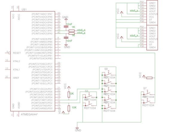
The accelerometers we used were analog so we did not have to use the I2C standard. The bumpers in effect are simple switches that trigger external interrupt pins and the servos are controlled by PWM outputs. Thus, there was no standard we needed to follow for our implementation.
Patents:
We have not been able to find any patents of similar devices. Even Roomba, the closest device in application, uses a completely different algorithm and set of sensors.
Program and Hardware Design top
Mechanical Design
The biggest component of the project was the mechanical design, which we didn’t fully realize till later. From the start we had a limited amount of materials to work with, we had one set of lego wheels and some lego parts. Due to the relative bulkiness of legos to a machined chassis, it was impossible to create a chassis that was at all slim and small while fitting the bulky servos and batteries. The basic mechanical design of the bot is a two wheeled structure with magnets glued to the bottom. The magnets are raised high enough so that they can apply a significant force without actually touching the board. From our testing, a couple magnets touching the board are strong enough to hold the bot permanently still. Thus, we had to go through a series of trial and error to find the right height. Originally for our chassis, we did not glue the magnets but instead we created small containers for each magnet with legos and thus kept them a constant thin piece distance from the board. However, this approach was abandoned because of the bulkiness of the legos led us to have very large boxes for each individual magnets. With the limited space we had on the bottom of the chassis, it was not quite possible to get a good grip on the board. We thus went ahead to gluing all the magnets and went through many days of trial and error.
- Slipping, the wheel needs a proper balanced grip on the board to move. This didn’t happen easily since our glued in magnets did not always provide an equal distribution of force on the easily bendable chassis. The chassis would bend from the strong magnetic force and cause one of the chassis to exert more force, and one end less. The wheels sometimes would be on the side of less force.
- Over gripping, the strong magnetic force was sometimes strong enough to pull the raised magnets completely to the surface of the board, thus bending or breaking the chassis. Once we reinforced the chassis, it was the tires of the wheels that started to give away. The wheels would get bent and the tires would get pulled off.
- Gravity, the unbalance of weight on the chassis caused our bot to never be able to move in a straight line on the board. Although we aligned the wheels and the bot was moving straight on the ground, the bot always curved downward on its horizontal path. We spent a few days trying to figure out a way to modify the chasis to fix this issue, but in the end we decided that having the accelerometer correct the course was the easiest and most reliable method. We also had to consider the effects of gravity on the bot as it is going up and down. Going up, the bot has to fight gravity full on and needs enough torque and grip. Going down, the bot needs enough grip to not slide from the momentum of the bot as it stops.
- Stability, the chassis is made of legos, which can be easily broken apart. Our only option to increase stability was to glue gun the parts, but we were restricted on what we could glue until we could create a suitable chassis.
- Eraser size, the chassis is built so that the eraser is raised slightly higher than any other part of the bot so that there would be considerate force on the eraser as it moves across the board. However, this causes the board to be raised up at an angle and disturbs the distribution of the magnetic force on the chassis.
- Circuits and wire weakness, since the bot requires a lot of physical handling and forcefully pulling and pushing, we often had to deal with the wires breaking, the solder breaking and wires shorting out each other.
Trying to deal with the above issues took up the majority of our time as some promising designs often ended up breaking after a few runs . Thus, we were constantly trying to find the perfect balance of grip strength. Too strong and we risk breaking parts, too weak and the bot slips.
From our trial and error we define the following points on the chassis that needs a strong grip:
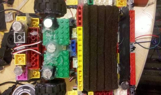
We needed a few magnets in the front side to keep the eraser down, but not so much that all the force is directed to the front. The back side, where the servo is attached, is where most of the force should go. The front side has a row of magnets that balances out the force of the magnets on the back so the chassis would not tilt back or forth too much, since the eraser causes the bot to be tilted. As seen in the picture, we glued every magnet with a large amount of glue, since the magnets snap off at the slightest weakness.
deally, the magnets are kept off from the surface of the board and the switches sweep on the surface. However, due to the strong force of the magnets, some magnets do stick slightly. The strong force of the magnet shown above is counteracted by the magnets on the other end of the chassis. Since there is a slight tilt to the chassis, the two ends counteract each others force.
The bot has bumper sensors attached to all four sides. These sensors are simply micro switches that trigger an interrupt pin. The switches are all glued to the sides of chassis, near the surface of the board.
Parts List:
| Part | Cost |
|---|---|
| Lego parts | $0 |
| 9 Volt battery | $2 |
| 2 six volt battery pack | $8 |
| Solder-board | $2.5 |
| Custom-PC board | $4 |
| Mega644 sample | $0 |
| sip or header socket/plug | $0.5 |
| DIP socket | $0.5 |
| 2 continuous servos | $28 |
| 2 single axis-accelerometer | $0 |
| Micro-switches | $4.5 |
| Neodynium magnets | $0 |
| total: | $50 |
For more detail: Autonomous Board Erasing Robot Using Atmega644