Summary of Battle Tank – A 3d Atmega32 Based Video Game
This project implements a wireframe 3D video game inspired by the classic Atari Battlezone, running on an Atmel ATMega32 microcontroller. The team developed a custom 3D vector engine to project objects onto a B/W TV screen using matrix transforms and Bresenham's line algorithm. Due to hardware constraints compared to the original arcade system, the final scope was scaled back, excluding fully implemented enemy tanks but retaining core movement and projection mechanics.
Parts used in the Battle Tank Project:
- STK500
- Whiteboard (2)
- Power Supplies (2)
- Custom PC board
- Mega32 (2)
- B/W TV
- Headers
- Dip Socket
Introduction
Our project is a wireframe 3D video game based on the classic Atari arcade game, Battlezone (Copyright Atari Corp, 1980).
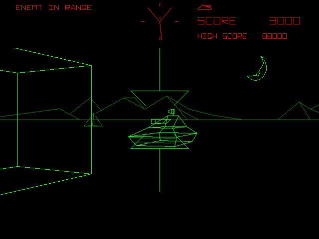
For those that have never heard of the game, Battlezone is a game in which the player maneuvers a tank through a flat environment, shooting and destroying enemy tanks while taking advantage of obstacles. Objects on the screen are rendered in wireframe 3D. The original game runs on a 1MHz, 8-bit Motorola 6502 MCU, and we figured we would be able to run a similar game on the 16MHz 8-bit Atmel ATMega32 MCU that we have been using all semester. Unfortunately, we did not take into account the corresponding hardware which literally drew the vectors onto the screen (controlled an electron gun and generated the image based upon vector commands input to specialized hardware), as well as the SRAM constraints and processing constraints which would pop up repeatedly. Thus, although our project does implement a basic 3d vector engine on the ATMega32, our project is much scaled back from our initial vision.
Figure 1: Screenshot from original Battlezone.
CAUTION: Although we have worked to minimize video flicker, patterns of flicker may still result at certain points. Those who are photosensitive should exercise caution when attempting to operate our project. Also, eyestrain may result from continuous play, please take time to rest with every interval of play.
High Level Design
The primary inspiration for our project stems from the classic 1980’s arcade game, Battlezone. As the hardware it was implemented on seemed basic, we thought that we could pull off something similar with the ATMEGA32 MCU. As mentioned above, significant changes had to be made as we realized the scope of the initial project.
The game runs on a simple wireframe 3D engine that we wrote. The following is a discussion of the basics of 3D rendering in relation to our engine.
Projecting the Game Objects onto the Screen:
In our implementation, game objects are represented by arrays of vertices (points) and edges forming polygons shaped as tanks, terrain obstacles, bullets, etc. This was our initial implementation – the final project differs from this, as mentioned later. The objects exist in 3D space, and are projected onto the television screen, a 128 by 100 2D space (in the actual implementation, we use only a fraction of this space to speed up processing and thus reduce screen artifacts).
The camera is fixed at the point (0,0,0), and points in the -z direction (we ended up pointing the camera in the +z direction in the actual implementation, the following figures were drawn prior to the change and thus point in the –z direction). The distance between the virtual camera and the screen is d. The width of the screen is 128 and the height of the screen is 100. Since the width of the screen is fixed, the viewing angle, shown as 2θ, is adjusted by adjusting d. The following figure illustrates the projection of a simple edge whose points have coordinates at (x1,y1,z1) and (x2,y2,z1), where z1 is negative and greater than the distance between the screen and the camera.
The red lines are drawn between the camera at the origin and the screen. The object and its projection onto the screen are drawn in gray. A green line and a purple line each connect one of the two points of the object to the camera at the origin, illustrating how the projection onto the screen is obtained.
To project the object onto the screen, the vertices (x1,y1,z1) and (x2,y2,z1) are taken and converted to the points (x1′,y1′) and (x2′,y2′). The formula for this tranform is simple – the x and the y components are scaled based upon their “distance” to the virtual camera, and a screen scaling terms which changes how much of the screen is viewed by the “camera”:
x’ = (x*d)/(z-zofCamera)
where x is the previous x coordinate, d is the aforementioned scaling factor, z is the object’s distance from the camera, and zofCamera is the camera’s location along the Z axis.
As zofCamera in this case is equal to zero, the formula collapses to:
x’ = (x*d)/(z).
The formula can be just as easily applied by substituting the Y term in for X, after which our x and y points are transformed into a basic camera perspective mapping. A line is then rendered between points (x1′,y1′) and (x2′,y2′) to complete the projection. The line draw algorithm we used is the same one utilized by Bruce Land’s code, which used a general Bresenham algorithm in order to determine the correct points to draw for a line. A short explanation of the basic algorithm follows.
Basic Bresenham algorithm: Start at a fixed x, and fixed y, and a fixed x,y endpoint. Calculate the dy/dx, and use it to calculate an error term. Increment the error term by dy/dx, increment the x row by 1, draw pixels in the correct direction, incrementing y, until the error between the calculated y term and the actual y term is zero, increment the error term by dy/dx, increment the x term by 1, and continue the algorithm until the given endpoint is reached, and a roughly optimal rasterized line will be drawn along a specified 2-space line.
The following figure provides an illustration of the aforementioned projection algorithm. The calculation of the x coordinate of the upper left vertex of the edge projected onto the screen. First, the horizontal and vertical green lines anchor the point and its projection onto x and y coordinate axes (drawn in black) at appropriate distances z. The intersection of the green line drawn between the point and the camera with the plane of the screen is the point we are trying to calculate.
A simple method to do so is to project the vertex onto the x axis, obtaining the point (x1,0,z1). Then, we draw a line from that projected point to the camera. The x value of the intersection of the line drawn from (x1,0,z1) to the camera with the screen plane will have the same x coordinate as the intersection of the line drawn between the original point (x1,y1,z1) and the camera with the screen plane, as can be seen from the figure below. We can draw two similar triangles (which are drawn in red) to calculate the x coordinate of the projection onto the screen.
An illustration of a projected line.
Thus, an object with n vertices requires 2n multiplications and 2n divisions to obtain the vertices of the projected image, from which each corresponding edge must be rendered. The multiplications can be substituted with much faster shift operations if d is set to a power of 2. We attempted to implement this optimization in our code, in order to speed processing. Also, note that this method works for edges whose vertices have different z coordinates (the projected line will be skewed appropriately) and for objects with a z distance between the camera and the screen (the projected line will appear stretched on the screen). Finally, in the example above, we fixed the camera at the origin, but the exact same method can be used to find projections for cameras located elsewhere on the z axis.
Using Matrix Transforms:
The figure below illustrates a bird’s eye view of the game field at one point in time. The green square represents the player tank, the magenta tanks represent the enemy tanks (the tanks ended up not being completely implemented in the final project, so substitute “target” for tank), the green circle represents a player projectile, and the magenta circle represents an enemy projectile. The red and blue lines represent the player’s angle of view and the screen. The blue line is 128 units long in the x direction, and on it, an object with width n units will appear as n pixels wide.
The camera, and hence the player’s “tank”, is fixed at the origin to prevent any unnecessarily complicated calculations, and hence, player inputs will move every other object in the game instead of moving the player tank. A forward move will translate all objects downwards (from the bird’s eye perspective), towards the -z direction. A backward move will likewise translate all objects toward the +z direction. This can all be performed by matrix multiplication.
The camera, and hence the player’s “tank”, is fixed at the origin to prevent any unnecessarily complicated calculations, and hence, player inputs will move every other object in the game instead of moving the player tank. A forward move will translate all objects downwards (from the bird’s eye perspective), towards the -z direction. A backward move will likewise translate all objects toward the +z direction. This can all be performed by matrix multiplication.
Where A is the transform matrix, x,y and z are cartesian coordinates, and w is a homogeneity term which allows for arbitrary non-linear transforms (in this case, since we translate our vertex by constant terms, we simplify by assuming that W is always equal to 1). By substituting entries into the various A entries, we can perform any sort of transform we wish on the X,Y, and Z terms. The translation of coordinates (x,y,z) by rotation around the X-Z plane is performed by the following matrix equation:
Parts List:
- STK500 – $15
- Whiteboard (2) – $12
- Power Supplies (2) – $10
- Custom PC board – $5
- Mega32 (2) – $16
- B/W TV – $5
- Headers – $0.40
- Dip Socket – $0.50
Total cost: $63.90
For more detail: Battle Tank – A 3d Atmega32 Based Video Game
- What is the primary inspiration for this project?
The project is primarily inspired by the classic 1980s arcade game Battlezone. - Can this game run on the same hardware as the original Atari version?
No, the original ran on a 1MHz Motorola 6502 MCU with specialized vector hardware, whereas this uses a 16MHz Atmel ATMega32 MCU. - How are game objects projected onto the screen?
Objects represented by vertices and edges are projected using a formula where x and y components are scaled based on their distance to the virtual camera. - Does the project use a fixed camera position?
Yes, the camera is fixed at the origin to prevent complicated calculations, so player inputs move all other objects instead of the tank. - What algorithm is used to render lines between projected points?
The project utilizes a general Bresenham algorithm to determine the correct pixels to draw for a rasterized line. - How does the code optimize multiplication operations?
The code attempts to substitute multiplications with faster shift operations by setting the scaling factor d to a power of 2. - What happens when the player moves forward in the game?
A forward move translates all objects downwards towards the negative z direction from the bird's eye perspective. - Are enemy tanks fully implemented in the final project?
No, enemy tanks were not completely implemented in the final project, so targets are substituted for them. - Is there a warning regarding visual effects during gameplay?
Yes, patterns of flicker may still result at certain points, posing a risk for those who are photosensitive. - What is the total cost of the parts listed for this project?
The total cost for all listed parts is $63.90.