Summary of BUILDING KILOBOTS AND REVISING KILOBOT DESIGN FOR IMPROVING THE OPTICAL RESPONSE
Summary: This thesis describes redesigning and building Kilobots in-house (WCU Kilobot versions 1.2–1.4), detailing PCB rework, soldering/debugging procedures, and hardware revisions to improve ambient light sensing and expand flash memory for large-scale swarm shape-formation experiments. Key changes include porting designs to Altium, increasing component spacing, lowering emitter resistance for the phototransistor (v1.3) to operate in brighter rooms, and replacing ATmega328P with ATmega1284 (v1.4) to provide more flash and I/O for a second light sensor.
Parts used in the Kilobot project:
- Battery
- Power jumper
- Vibration motors (two)
- RGB LED
- Ambient light sensor (phototransistor)
- Serial output header
- Direct programming socket / ISP header
- Charging tab (removed in WCU design)
- Infrared transmitter
- Infrared receiver
- Microcontroller ATmega328P (original design)
- Microcontroller ATmega1284 (version 1.4)
- Op-amp (U6 as referenced)
- Resistors (including emitter resistor R35)
- Capacitors
- SMD components (no smaller than 0603 in WCU builds)
- PCB board and stencil for solder paste
- Solder paste (SMD291AX10T5)
- Reflow oven
- Hot air gun and solder wick
- Tweezers and magnifier / microscope
- Kilobot charger docking station (3D printed, 5x5 chambers)
- USB AVRISP XPII bootloader programmer (with modified cable)
- Overhead Controller (OHC)
- Computer with KiloGUI and Kilobotics online editor/compiler
I would first like to acknowledge my adviser, Dr. Yanjun Yan, for her patience, kindness, and most
of all her assistance in completing this thesis. I would like to thank Dr. Martin Tanaka, Dr. Peter
Tay, and Dr. Paul Yanik for serving on my thesis committee.
ABSTRACT
Inspired by the emergent behavior of swarms, we want to eventually use a distributed selforganizing swarm of robots for shape formation. To verify the idea using real robots in the experiment, we need to first build more Kilobots to enlarge our repository of Kilobots. Kilobot is a kind of small robot with a 33-mm diameter that was originally designed by Harvard in 2012 and redesigned at WCU with the simplified building process in 2016 (WCU Kilobot version 1.1).
Based on the earlier design, we have redesigned the Kilobots further (with three revisions in version 1.2, 1.3, and 1.4). This research work describes the challenges and solutions in building and debugging Kilobots, as well as the planned shape formation operation. Kilobots are built inhouse using reflow soldering for surface mount components and hand soldering for through-hole components. A systematic debugging procedure, as well as the most commonly seen issues and their solutions, are described based on our building and testing experience. The WCU Kilobot version 1.1 was designed in PADS, and yet we no longer had the license in PADS. Therefore, we redid the schematics and PCB layout in Altium Designer, and enlarged the spacing between the crowded components, in WCU Kilobot version 1.2. Although the design of version 1.2 was nearly the same as in version 1.1 with only added spacing, it was redone in Altium Designer that we could continue to maintain a license, and hence our later revisions were possible. In shape
formation, a phototaxis movement (moving away from light) is the driving force in the largescale reductive approach, and yet the original Kilobot design allows such movement only in a dark room because of the ambient light sensor output is saturated at a low illumination level. An experiment was conducted to examine the saturation of sensor reading at increasing lux levels with different phototransistor’s emitter resistances, and a new resistance value of emitter resistance was proposed and implemented in our Kilobots (version 1.3), to ease the experiment
lighting condition, making it more lenient and convenient than before, even at daylight. An earlier capstone experiment in 2018-2019 seemed to indicate that the flash memory of ATmega328P, the microcontroller on the Kilobot, was not enough to handle the calculation when more than three Kilobots with known or calculated locations were used for multilaterationbased locationing for the next robot that needed to calculate its location. To address this issue, we have updated the design of Kilobot to replace its ATmega328p (with 32 Kbytes memory)
microcontroller with ATmega1284, which has 128 Kbytes of flash memory for programming
(version 1.4). In addition, we also inspected the feasibility of installing two ambient light sensors
at opposite sides of the Kilobot and found the version 1.3 was more sensitive than version 1.1 to
provide distinctive readings even at a distance increment of one Kilobot diameter, which meant
that the Kilobot could easily tell the direction of the light with two sensors. Given the new
microcontroller in version 1.4 with more IO channels, we further revised it to add a second
ambient light sensor, which will help to give us more control on the Kilobot when they perform a
light based movement, such as in shape formation.
INTRODUCTION
The role of robotics is to take on the jobs that are repetitive, requiring high accuracy and
precision, or not executable by a human being. The application of robotics has increased the
gross industrial productivity to a large extent. The Single Robotic System (SRS) has been
applied in industries and research institutions for many complex functionalities. However, there
are some situations when swarm robotics will be more convenient than a single robot to apply a
group of small robots to perform a complex operation. This type of swarm behavior can be also
observed in nature. For example, flocks of birds, schools of fish, and a colony of ants organize
themselves to form a unitized cluster to perform complex action. Inspired by nature, researchers
have started to integrate groups of small robots to work together to complete a complex task by
applying robots that have very basic functionality. The researchers had developed various
platforms and programming tools for swarm robotics. In most cases, the small robot
communicates only within a limited range requiring an efficient control strategy. Kilobots were
initially designed by Harvard University in 2012 and redesigned for construction simplicity at
WCU in 2016. It is one of the widely used platforms that researchers have used on both hardware
and software design for swarm robotics. The WCU Kilobots lab has explored the control strategy
in the Kilombo simulation environment earlier and sponsored multiple capstone projects on
scaling up the localization ability of the physical Kilobots. To continue the efforts, we need to
build more Kilobots.
Shape formation is a popular task in swarm robotics. In shape formation, the algorithm
can be grouped into two main categories, i.e., additive process and subtractive process. In the
additive process, materials become adjoined and fused to form the desired shape, or the robots
cluster together and move along the boundary of the cluster until they find a position to stay to be
part of the cluster of the desired shape. In the subtractive process, materials are reduced from the
initial bulk amount, or the robots are placed densely together initially, and the robots outside of
the desired shape move away automatically often driven by a light source in the center. Both
processes have pros and cons when it comes to practical application. In the additive process, the
individual robot’s movement may depend on the rest of the group, and hence it takes a
comparatively long time to be aligned. On the other hand, in the subtractive process, a bulk of
robots is needed initially to be chiseled away and hence the needed number of robots is big, but it
will take much less time to form a shape than in the additive process. One potential solution is to
combine both additive and subtractive processes in shape formation so that the desired shape
may extend beyond the original cluster boundary, and the robots not inside the shape will move
along the cluster boundary to fill in the void instead of simply moving away. In all processes, we
need a sizable amount of robots to perform practical swarm experiments, and we also need to
understand how Kilobots navigate according to the light source as a building-block movement in
shape formation.
In our original version of WCU Kilobot version 1.1 built in 2016 following the Harvard
schematics but in a different layout, the robot can perform phototaxis movement only in a dark
room by design, which is not so convenient. So, in this research, we focused on building more
Kilobots to conduct experiments with more flexibility in the regular room condition than before.
As a result, this thesis focused more on hardware development. We have inspected the pros and
cons of the earlier design, provided three revisions (versions 1.2, 1.3, and 1.4) so that it can be
built and debugged easily in-house while enabling us to conduct experiments in a regular
daylight environment.
1.1 Objectives
Kilobot is one of the commonly used robots for swarm robotics tests and developments.
Purchasing Kilobots is expensive and it does not give the students a solid experience to
understand the Kilobot hardware. In-house building and debugging can help students understand
the operations and discover some aspects that they can work with for further development. The
main goal of this research is to build and revise Kilobot in-house to support swarm robotics
experiments. The main objectives of this research include the following:
• Create guidelines on building and debugging Kilobot in-house based on our building
experience.
• Update the design to allow a more flexible experiment environment than before.
• Verify the performance of Kilobot that we built in relevant experiments.
• Increase the number of Kilobots.
1.2 Significance of the study
This research was conducted to scale up the Kilobot construction in-house to eventually
carry out the shape formation operation. In the WCU Kilobots lab, subtractive shape formation
operation for a simple shape (square) at a small scale (using 16 robots in a 4 by 4 pattern)
without using the light source has been explored, and yet we need to scale up the experiment to
allow a more complex shape using the light source in the center of the shape as a driving force
for the movement. Meanwhile, we are exploring the additive shape formation and to fuse both
processes together. For all the potential experiments, we need to enlarge our repository of
Kilobots. While building Kilobots in house, the building and debugging experience have been
used to update the design that will improve the process as well as the light-sensing based
movement. The outcomes of the research are listed below:
• The debugging guidelines summarized from our efforts are helpful for the future
building process.
• The robots now have a wider operating range of lighting conditions than before.
• The robots could have more flash memory for large scale operation.
• We could have more control of the robots with an added sensor
BACKGROUND
2.1 Swarm Robotics
Swarm robotics is the coordination of a multi-robot system, which consists of a large
number of simple features with small robots. The collective behavior of insects or animals can be
imitated by swarm robots in swarm intelligence. Swarm robotics encompasses the design of the
robot and control strategies. A key advantage of swarm robotics is the ability to adapt any team
member as needed that reduces the chance of failure due to the unavailability or malfunctioning
of any individual during the operation. The definition of swarm robotics by Shahin [1] gives an
insight into this field.
“Swarm robotics is the study of how a large number of relatively simple physically
embodied agents can be designed such that a desired collective behavior emerges from the local
interactions among agents and between the agents and the environment.”
There is a lot of platforms to perform simulation and practical test of swarm robotics like
Khepera robot [2], e-puck robot [3], Jasmine robot [4], I-Swarm robot [5], S-Bot [6], Kobot [7],
SwarmBot [8], Kilobot [9] and so forth. Kilobot is one of the popular platforms for swarm
robotics that was developed at Harvard university to program and experiment with collective
behaviors in large-scale autonomous swarms [10]. The WCU Kilobot team [11] poses a modified
design of Kilobot that was built and tested at WCU in 2016.
2.2 Kilobot System
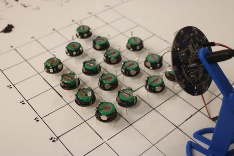
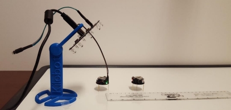
Kilobot system consists of Kilobot itself, an overhead controller (OHC), the Kilobot
charger, a bootloader programmer, and the programming environment. After a Kilobot is built
and debugged, it is charged by a charging station that can charge 25 robots at a time. The
bootloader we used is loaded through a USB AVRISP XPII, AVR Programmer, with a modified
cable connection for interfacing with Kilobot. We have used Kilogui, a graphical user interface
for interfacing the OHC to the computer, and OHC has been used to program the Kilobots by
sending programs via IR communication, as shown in Figure 1. The Kilobot is programmed
using a C based programming language, and we have used an online compiler, Kilobotics
website[12], maintained by Harvard University to write and compile the program.
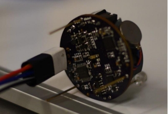
2.2.1 Kilobot
Kilobots are microrobots with a 33-millimeter diameter that has several basic
functionalities. It communicates with other robots by infrared. Its microprocessor can process
data and make decisions. It moves based on the slipstick phenomenon using two vibration
motors mounted on two out of the three legs. It was designed to be used in large quantities.
Figure 2 shows the parts of a Kilobot [13]:
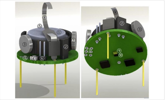
Part-1 shows a battery to supply power to the robot for its functionality. Part-2 is the
power jumper used for turning on and off the robot. Part-3 is the vibration motors to enable the
movements. Part-4 shows an RGB LED, which is used to indicate the various status of the robot
during its functionality. Part-5 is the ambient light sensor that is used for the light-based
operation. Part-6 is the serial output header, which is used to output serial data to the computer
for debugging purposes. Part-7 is a direct programming socket that is used to load the firmware
to the microprocessor unit of the robot. Part-8 is the charging tab, which has been removed in our
WCU revised design as a new charger was designed at that time. Part-9 is the infrared transmitter
to transmit IR signals to other robots. The last one, part-10, is the infrared receiver, which is used
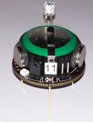
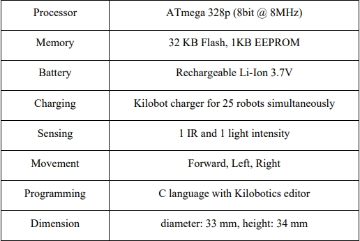
to receive the infrared signals from other robots or the OHC. Figure 3 shows the previously built
WCU Kilobot version 1.1, which used nearly identical schematic to the Harvard design but with
a compact layout, and the SMD components were no smaller than 0604 for in-house fabrication.
Table1 shows its main specifications.
In short, a Kilobot contains a microprocessor to make decisions, a rechargeable battery to
enable its action, an IR transceiver for sensing and transmitting a signal to other Kilobots or
OHC, and a motor vibration based slipstick movement system. We program it using C in an
online editor at the Kilobotics website.
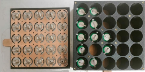
2.2.2 Kilobot Charger
To conduct a swarm robotic experiment such as shape formation, we need a lot of robots.
Charging all the robots individually is tedious and time-consuming. To simplify the process, a
Kilobot charger storage case is used. It is a 3D printed box [14], with 5 × 5 cylindrical
chambers inside for placing each individual robot. The bottom and the top of the box are inserted
two copper plates with springs on top to make electrical contact for charging. It can charge 25
Kilobots at a time by using a laptop charger rated at 19.6V, 4.62 Amp. Figure 4 shows the
charger docking station for our WCU Kilobots.
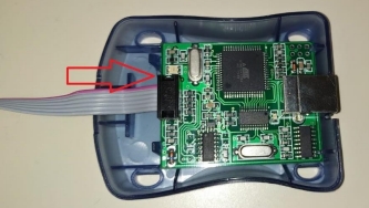
2.2.3 Bootloader Programmer
We are using the USB AVRISP XPII as the bootloader programmer of our Kilobot.
When a Kilobot is built and charged for the first time, it needs to have a bootloader driver. A
bootloader programmer is very convenient to load the bootloader file into a Kilobot
microcontroller. We are using Atmel Studio to interface with Kilobot using a bootloader
programmer. Figure 5 shows the image of the bootloader programmer.
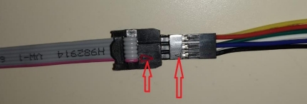
This programmer comes with a serial peripheral interface that is primarily designed for
Arduino and some other similar devices. Since the physical orientation of the Kilobot interface
port is different, we have modified the interface of cable to establish ISP communication with the
Kilobot. Figure 6 shows the modification of cable for connecting the WCU Kilobot. Figure 7
shows the connection of Kilobot with the programmer using our modified cable.
2.2.4 Overhead Controller
Programming each Kilobot through cable is tedious and nearly impossible for thousands
of Kilobots. So, the Harvard University Kilobot team provided the design of an overhead
controller for programming Kilobots using infrared signals. WCU built the overhead controller
in-house earlier to program all the robots by interfacing them through IR. The coverage area is
about a circle of one-meter diameter for programming [15]. Figure 8 shows the overhead
controller of the WCU Kilobot system [16]. Note that a serial cable is connected between the
OHC and a robot in Figure 8, that is to send serial data back to the computer through the OHC.
For programming purpose alone, the IR transmission from the OHC to the robots is wireless.
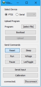
To interface with the overhead controller through a USB cable from the computer, a
graphical user interface app called KiloGUI, as shown in Figure 9, is used [16]. KiloGUI can be
used to calibrate the Kilobot motors and assign its ID, and to send a program from the computer
to the OHC, to distribute it to the robots eventually. This app is user-friendly with a serial
reading window. When the robot is connected to the OHC through a serial cable, as shown in
Figure 8, KiloGUI can read the data from the robot such as ambient light sensor output or the
calculation results during an experiment, which is essential for debugging.
2.3 Programming Environment
We used the online editor and compiler Kilobotics [13] as the programming platform.
This software system was designed by Alex Cornejo and Mike Rubenstein, and is maintained by
the Harvard Self-Organizing Systems Research Group. Using this system, we can write the
program on the web that is stored as a C file in a dropbox. The program is compiled online using
built-in libraries there, and the generated hex file is downloaded into the dropbox directory. The
programming environment consists of the following components.
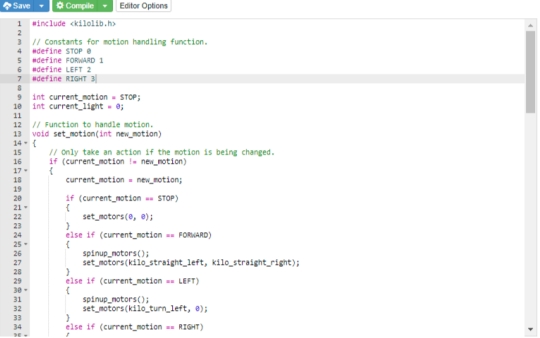
Kilobot Library: The Kilobot is programmed in C. On the Kilobotics online editor, the
libraries related to robotics movement and communication (controlling motors, sensors, and
navigation, and so on) are all installed and accessible by default.
Editor and Compiler: The Kilobotics online editor allows us to write and compile
programs for the Kilobot. It uses Amazon servers for compilation, and as a user, we can store all
of our C program files and the compiled hex files in the dropbox directory. The Kilobot program
can also be compiled locally, but mostly, we have used the online compiler, which is easy to use,
with debugging information inside the editor, as shown in Figure 10.
2.4 Shape Formation
Shape formation is a popular task for swarm robots. There are two common processes of
shape formation, i.e., subtractive shape formation and additive shape formation [10], [17]. In
both cases, there are some advantages and disadvantages. In subtractive shape formation, a lot of
robots that are not part of the desired shape finally move away. On the other hand, in the additive
approach, it is likely that the shape border may be incomplete due to a random combination of
the robots and the geometric form of the desired shape.
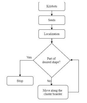
2.4.1 Subtractive Shape Formation
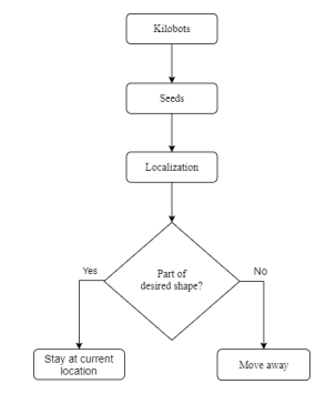
Subtractive shape formation is relatively simple in that the robots within the desired
shape do not need to move. However, it requires a large number of robots to contain the shape
initially. First, we will gather all the robots as a group and let them figure out their location
through multilateration. Then based on the desired shape, each robot will decide whether it’s
inside of the shape or not. If it’s not a part of the shape, it will evacuate itself from its position
away from the cluster where the in-shape robots remain. Thus, the shape will be formed as
demonstrated in the flowchart in Figure 11.
In this process, there is a possibility that a lot of robots may not be a part of the shape and
hence those robots do not contribute to the final shape. It is a limitation of this process. On the
other hand, this process is fast when the robots that need to move away are guided by a light
source. We need a lot of robots to perform this test in the lab, and all the robots should be of the
same dimension and similar in nature to interact with each other. The previous design of WCU
Kilobot version 1.1 can perform light intensity related tasks only in a dark environment. To
perform in the room-light condition, the ambient light sensor circuit needs to be adjusted.
2.4.2 Additive Shape Formation
Additive shape formation is a comparatively complex action that overcomes the
limitation of the subtractive shape formation, where some robots move away from the desired
shape to be not used eventually. But in the additive approach, all the available robots can
contribute to forming the shape as shown in Figure 12.
In additive shape formation, the robots move along the cluster of other robots until they
stop at a position and contribute to the desired shape. This process is typically lengthy and slow.
However, it complements the subtractive approach and it is beneficial to combine both
approaches to achieve both speed and accuracy
METHODOLOGY
3.1 Building and Challenges
We have built Kilobots here at WCU and experienced the building and debugging
challenges. The building process was tedious when debugging was an essential step. There were
still PCB boards available from the last design at WCU, Kilobot version 1.1, on 3 by 3 panels.
The SMD components were no smaller than imperial 0603 size (0.06 inch by 0.03 inch, or 1.55
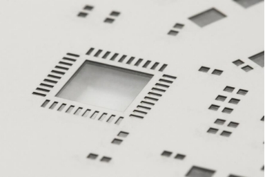
mm by 0.85 mm). We ordered a stencil, as shown in Figure 13, to go with the PCB board while
applying the solder paste. Once we aligned the stencil and the PCB board well and taped them in
place, we spread a thin layer of solder paste onto the stencil so that an appropriate amount of
solder was applied to the PCB.
Then we used a tweezer to place the components onto the board, which would stay in
place due to the slight viscosity of the solder if the board was not shaken, and then the board was
baked in an electronic reflow oven nearby our working bench minimizing the unintended
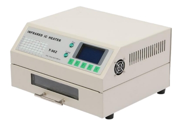
displacement of the components before baking. After all the components were placed, we first
visually examined the board with a 10x zoom lens to check if there is any unexpected short, and
we could fix those short before the board was baked in a reflow oven. The reflow oven we used
is shown in Figure 14.
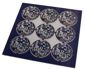
After being baked, the circuit boards would look like Figure 15. There were typically
numerous shorts as the solders would melt and spread during the heat treatment. Our debugging
procedures are described in the following section.
The previous Kilobot design (WCU Kilobot version 1.1) has already replaced all
components in the original Harvard design to be no smaller than 0603 packages, but soldering by
hand is still a challenge to place the SMD components. The spacing between the components is
tiny, making it difficult to avoid unexpected short circuits. Some regions on the board are more
crowded than the others, and those regions often need to be debugged.
To reduce unexpected shorts, we choose the SMD291AX10T5 solder paste with a mesh
size of T5 where the solder particles are the smallest on the market (15-25 µm, on average). We
have also ordered a new stencil with even thinner slots than before, to leave less amount of
solder onto the PCB board. Both adjustments helped us to reduce unexpected shorts.
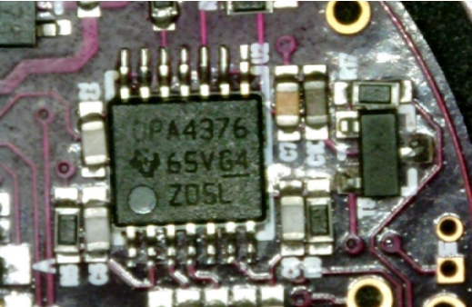
As an example of debugging such unexpected shorts, Figure 16 shows a microscopic
view of the board before the debugging, where there were unexpected shorts between the leads
on the bottom side of the chip. The IC chip, labeled as U6 in the schematic, is an op-amp with
seven leads on two sides of it. To examine it, we used both the 10x zoom lens for eye-viewing
and the pico zoom of the electronic magnifier that displayed the view on the computer monitor.
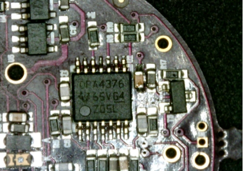
Figure 17 shows the board after the debugging, where the leads at the bottom side of the chip,
U6, were separated.
Even if the circuit was built carefully, it was almost impossible to avoid unexpected short
circuits. So debugging was an essential step while building Kilobots. There were mainly three
scenarios of unexpected shorts: (i) There was some unexpected short due to excessive solder
paste, but the excess solder was visible; (ii) The short was caused by the displacement of the
components so that two components came in contact with each other directly; (iii) The solder got
under the chip excessively, which was not accessible nor directly debuggable, and we should not
heat the chip too much to damage it.
In the first situation, we heated the board using a hot air gun and took the extra solder
paste away with solder removal wick wire.
In the second situation, there was no way to get rid of short by simply removing the
solder. We had to reposition the components. Therefore, we heated the components carefully and
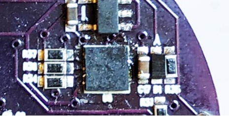
repositioned them using a tweezer. For example, Figure 18 shows the squire chip in the center
(labeled as U2 on the schematic) is surrounded by a group of three resistors on its left and a
capacitor and two other components on its right. There was no adequate space between the chip
and its adjacent components to debug the chip U2. We had to remove the adjacent components to
fix the unexpected short of the chip beneath it and then re-mounted those surrounding
components back to their original positions. The whole process was time-consuming and very
inconvenient. So, to eradicate this issue in our revised design, version 1.2, we have increased the
spacing between the components.
In the third situation, it was very tricky to find such a short and fix it, but fortunately, it
was rare in my building experience. Sometimes the main microcontroller unit was shorted at its
bottom, which was not visible even in a microscopic view. After thoroughly debugging a board,
if I still couldn’t get a reasonable impedance between the battery opening and between other
measurement points, I would assume this internal short issue. I found several cases of this issue
and fixed them by heating the microcontroller carefully. Most of the chips, including the
microcontroller, can tolerate a heat source of 120° C from a reasonable distance for no more than
30 seconds continuously. Sometimes there was unexpected short at the bottom of the chip so I
had to heat it to loosen the solder. I would heat the chip for about 15 seconds at a temperature of
110° C and then pushed it from the top to press the excessive solder out. Then I use the solder
removing wick wire to get rid of the extra solder.
3.2 Light Based Operation
Kilobots is equipped with an ambient light sensor useful for the operations based on light
intensity. The ambient light sensitivity of the previous designs (Harvard and WCU version 1.1) is
suitable only for simulations in a dark room. We aimed to update the Kilobot design in WCU
version 1.3 to operate them in a more tolerant lighting condition than in a dark room [18].
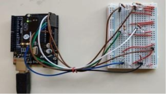
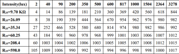
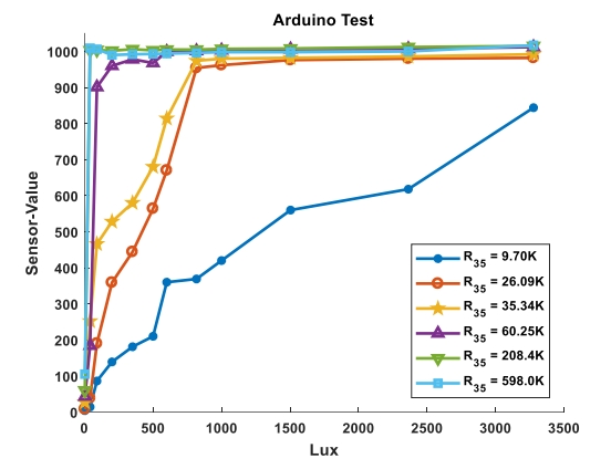
To examine the ambient light sensor, we built an equivalent circuit using Arduino Uno
and the same kind of phototransistor used in Kilobot. A suite of emitter resistance values (from
the existing design’s 608 kΩ down to 10 kΩ) was used to measure the output voltage at various
illumination lux levels, as shown in Figure 19. The exact resistor values were measured and
recorded in Table 2, and then the sensor output at various lux values was measured and reported
in Table 2. The same data were plotted in Figure 20 for easy visualization.
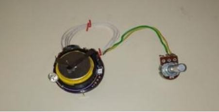
Next, we replaced this particular resistor on Kilobot, labeled as R35 in the schematic, by a
potentiometer soldered onto the board, and tried the same experiment using the serial channel of
the KiloGUI, as shown in Figure 21.
We tuned the potentiometer to be exactly the same resistance as what we used in the
Arduino test. The result was reported in Table 3 and plotted in Figure 22. We found that both the
Arduino and the Kilobot experiments were consistent to show that the smallest resistance in our
test is the best to achieve decent sensitivity and range. If this resistance was set to be even
smaller, we would lose out on the output range and incur too much current in this phototransistor
circuit, which was not desirable, either.
Source: BUILDING KILOBOTS AND REVISING KILOBOT DESIGN FOR IMPROVING THE OPTICAL RESPONSE
- How was the Kilobot PCB reworked to allow continued development?
The WCU design was redone in Altium Designer (version 1.2) with increased spacing between crowded components so the team could maintain a PCB license and continue revisions. - Can Kilobots operate in normal room lighting after revisions?
Yes. In version 1.3 the emitter resistor for the phototransistor was changed (based on experiments) to increase ambient light sensitivity so Kilobots work in more lenient lighting conditions including daylight. - What change was made to address limited flash memory on the Kilobot?
The ATmega328P (32 KB flash) was replaced with an ATmega1284 (128 KB flash) in version 1.4 to provide more program memory. - Does the revised design support directional light sensing?
Yes. Version 1.3 showed improved sensitivity and in version 1.4 a second ambient light sensor was added to help determine light direction. - What soldering and assembly methods were used to build Kilobots in-house?
Surface-mount components were placed with a stencil and reflow soldered in an oven; through-hole components were hand-soldered. Solder paste SMD291AX10T5 and a tweezer, hot air gun, and solder wick were used for debugging. - How were common PCB shorts debugged during assembly?
Visible excess solder was removed with solder wick and hot air; displaced components were reheated and repositioned; hidden bottom-of-chip shorts were addressed by careful heating (around 110–120°C briefly) and pressing solder out, then cleaning with wick. - What tools are used to program and interface with Kilobots?
Programs are written/compiled via the Kilobotics online editor, hex files transferred via the Overhead Controller (OHC) using KiloGUI, and initial bootloaders loaded with a USB AVRISP XPII programmer and modified cable. - How are many Kilobots charged efficiently?
A 3D-printed charger docking station with 5×5 chambers and copper plates charges 25 Kilobots at once using a 19.6V laptop-style charger.