
Summary of Controlling internal DAC AT90PWM3 using microcontroller
This article outlines a digital voltage control unit project using the AT90PWM3 microcontroller. It details the specific hardware components required and provides C-style assembly code to configure the internal DAC, set voltage references, and output 10-bit values to pin D2A for precise voltage regulation.
Parts used in the Digital Voltage Control Unit:
- AT90PWM3-16SQ
- SLO2016 LED display (2 units)
- 22uF/25V elco SMD
- 0.1uF/16V tant. 1206 capacitors (2 units)
- 10 kOhm 1206 resistors (2 units)
- 100n multilayer 1206 capacitors (3 units)
- 10uH SMD coil
- Sharp rotary encoder
1x AT90PWM3-16SQ
2x SLO2016 LED display
1x 22uF/25V elco SMD
2x 0.1uF/16V tant. 1206
2x 10 kOhm 1206
3x 100n multilayer 1206
1x coil 10uH SMD
1x rotary encoder (Sharp)
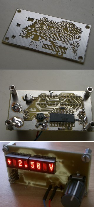
Digital voltage control unit
his is how a value is stored into the DAC registers. First you have to set the voltage reference (REFS0=1 and REFS1=0 means internal reference), which is the same as the ADC reference, and then enable the DAC and the DAC output.
ldi temp, (1<<REFS0) sts ADMUX, temp
ldi temp, (1<<DAEN)|(1<<DAOE)
sts DACON, temp
Now you can set a 10-bit value in e.g. the Y registers and output on pin D2A of the AT90PWM3.
sts DACL, YL
sts DACH, YH
For more detail: Controlling internal DAC AT90PWM3 using microcontroller
-
How is a value stored into the DAC registers?
First set the voltage reference by setting REFS0 to 1 and REFS1 to 0, then enable the DAC and DAC output. -
What does setting REFS0=1 and REFS1=0 mean?
It means using the internal reference, which serves as the same reference for both the ADC and DAC. -
Which pin is used to output the DAC value?
The value is output on pin D2A of the AT90PWM3 microcontroller. -
How do you enable the DAC functionality?
You enable the DAC and the DAC output by writing specific bits to the DACON register. -
What size value can be set for the DAC output?
A 10-bit value can be set in the Y registers and output to the pin. -
Which registers store the low and high bytes of the DAC value?
The low byte is stored in DACL and the high byte is stored in DACH.
