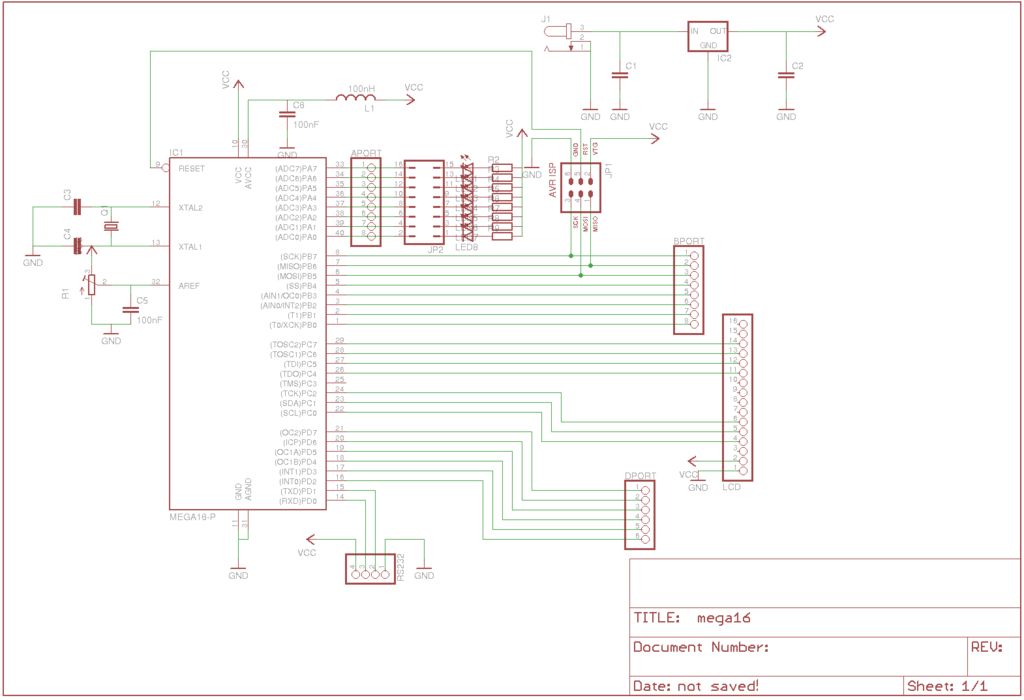
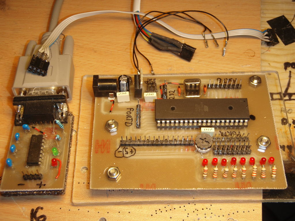
This instructable shows, how to do your own development board for Atmega16 or Atmega32 processors.The Internet is full of home made development boards, but I think that, there is room left for another one. This board have been very useful on my projects and I actually designed and made it to serve one of my project.
What it offers?
– ISP-connector.
– Adjustable reference voltage for AREF with trimmer.
– 8 leds connected PORTA with removable jumpers, so you can use leds also with another ports.
– Spike bars for PORTA, PORTB, PORTC and PORTD.
– Modified spike bar for LCD-screen (4 bit)
– rs232 serial port connector
– Removable rs232 module
– Regulated 5V
What you will need? (parts for main board)
– 1x Atmega16 or Atmega32 processor
– 1x crystal (It is your choice how many Mhz it will be)
– 2x 27 pF capacitors for crystal
– 1x 7805 voltage regulator
– 1x 47uF 16V capacitor
– 3x 100nF capacitor
– 1x DC-jack 2,1mm or 2,5mm (what ever you want use)
– 1x 1K potentiometer
– 8x led (any colour)
– 8x 330 Ohm resistors
– lot of spike bars
Parts for rs232 module
– Max232 IC
– 4x 0,1uF capacitors
– 2x led (green and red)
– 2x 330 Ohm resistors
– Spike bar
– D9-connector
Step: 1 The Circuit Boards
There is circuits from the both boards and the pdf-file contains print out files from these boards. You can etch your boards from these pictures. The zip-file contains all Eagle-files from these boards. Feel free to modify these how do you want.
Step: 2 Etching or Milling
There is two ways to make these boards, etching or milling. I’m not a chemist, so I used the last option. I made my mill from these great instructables, so If someone have also nc-mill and want to use it for make these boards, just let me know and I will send the G-codes.
Step: 3 Soldering
Step: 4 Testing
Before we can test our development board, we are going to need AVR-programmer cable. Here is good instructable about the programming cable. We need only 6 wires. SCK, MISO, MOSI, RST, Ground and +5V and that’s why my connector have only 6 pins.
IMPORTANT! SCK, MISO, MOSI and RST signals needs 390 Ohm resistors which are usually soldered on board, but I wanted save some space from the board and that’s why the resistors are inside the cable. Without these resistors programming won’t work.
We also have to do a cable between rs232 module and the main board.
There is also couple “test wires” on the picture and these are really useful when we are going to test our board.
For more detail: Development Board With LCD using Atmega16 microcontrollers


