Download the AVRStudio assembly source (HTML format): morbcna.html
Download the AVRStudio Hex (Intel Intellec 8/MDS format): 050219A.hex
Project Overview
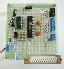
hoto 1. The Low Cost Telemetry Device is composed of an ATMega8, a
serial interface, and some decoupling components. A crystal is not needed.
OVERVIEW
The Low Cost Telemetry Device (LTD) provides a low cost, minimal parts count Telemetry keyer using an Atmel’s ATMega8 Microcontroller. The LTD sends data by measuring voltage levels of up to four analog channels via its on-chip 10-bit Analog to Digital Converter (ADC) and converting them to numbers and sending the measurements via Morse Code. There are two signal outputs – one is a binary Morse Code signal such as would be used to key a Continuous wave (CW) transmitter, and the other output is tone modulated and could be used to drive a small speaker to the audio input of a transmitter.
Options allow setting code speed to 25, 10, 5 or 1 word per minute, 1 kHz or 500 Hz tone, and measuring 1, 2, 3, or 4 analog channels. The options maybe set with jumpers or with and EIA-232 terminal, and in the case of setting it up with a terminal, a text string of up to 80 characters maybe sent along with the data. Terminal settings are 9600 Baud, no parity.
Thoroughly Modern Morse
Morse code , now over 150 years old, has long since faded from use by Coast Guard, Navy and other Military Services in favor of modern communications modes usually carried over microwave or Satellite links.
So one must ask , why use Morse code when we have things like Bluetooth or 802.11 to send data? The answer is simplicity and reliability. When Samuel Morse demonstrated the Telegraph to Congress in 1844 it was clear that one of the key features of his device was simplicity. Only later would the use of RF demonstrate it’s robustness in poor RF conditions. Besides it’s reliability, good signal to noise ratio and simplicity factor, Morse code has one more feature that makes it thoroughly modern: the ability to be decoded by human ear.
Morse Code still has millions of Amateur Radio fans around the world who swear by it’s ability to “get through” when RF conditions are poor. Although no longer used as the defacto communications mode it is still required knowledge by military Special Forces and some Amateur Radio Operators licenses.
In the special case of Amateur Radio use, the data identification string can be programmed into the controller to provide proper ID or other supplemental information when using the device as a repeater controller or automatic keyer. For example, Amateur Radio Operators can use the LTD as a Contest Keyer by turning the analog to digital channels off and entering a text “CQ” message.
The range of uses also includes amateur rocketry and unmanned balloons, repeater station operating parameters, manufacturing process parameters, or liquid levels such as those in fuel tanks or water courses.
Teaching a Micro to Tap Dance -Hardware Overview
As mentioned above, the simplicity of hardware was a prime concern for this project, so naturally a single ATMega8 Microcontroller would do the honors (see figure 1). This chip was turned into a smart Morse code operator while making use of the chips Analog to Digital conversion feature. For this project the 28 lead PDIP version of the device allows for 4- channel 10-bit ADC input operation as easy prototyping.
The controller firmware, which is described in a separate section, contains routines to scan from one to four 10-bit analog input channels and send the measurements by Morse Code as determined by either jumper settings, or parameters set with a serial terminal and the parameters stored in the chips internal EEPROM. When the parameters are set with a serial terminal, a text string of up to 80 characters may be optionally sent along with the measured voltages.
If operation is not set up with a serial terminal, operation is determined by the setting of hardware jumpers to ground (the chip has internal pull-up resistors of about 50k Ohms.), and one special jumper will force the jumper selections to override any previous setup information stored in the on-chip EEPROM.
Here are the jumper selectable settings.
Default Operation (PDIP Pin 11)
When this pin is grounded, operation is determined solely by the jumper configuration, meaning that all parameters stored in EEPROM will be ignored, though those parameters may still be edited if an EIA-232 terminal is connected.
Tone (1 Khz.500 Hz) select (PDIP Pin 5)
The state of this pin determines whether the Morse Code Tone output frequency is 500 Hz or 1 kHz.
Open = 1 KHz tone
Grounded = 500 Hz tone
ADC channels selection (PDIP Pins 4 and 5) The states of these pins in combination determine whether 1,2,3, or 4 ADC channels will be measured.
Pin 5 Pin 4 Channel(s) measured
Open Open Channel A only
Ground Open Channels A and B only
Open Ground Channels A, B, and C only
Ground Ground Channels A, B, C, and D
Morse Code Speed (PDIP Pins 27 and 28).
Pin 28 Pin 27 Morse Code Speed
Open Open 10 Words per minute
Open Ground 1 Word per minute
Ground Open 5 Words per minute
Ground Ground 25 Words per minute
The 1 word per minute code speed is intended for very low speed computer-to-computer radio communications where the signal-to-noise ratio is very poor.
Note that grounding Pin 11 and leaving the other pins floating will result in only analog channel A being repeatedly measured and sent at 10 words per minute, with a 1 kHz tone.
The LTD circuit is pretty much an ATMega8 running with its internal 4 MHz clock, along with a power supply and an optional EIA-232 buffer. In the simplest implementation, the EIA-232 buffers may be omitted and operation set only by grounding selected pins.
Unused inputs on the ATMega8 are held high by the chips internal pull-up resistors to prevent the pins from floating between logic levels, thus potentially saving a few milliwatts of power dissipation.
The RXD input also has an internal pull-up resistor, so that if a discreet transistor EIA232 buffer is used instead of the MAX32, a pull-up resistor would not be needed on the RXD input.
Construction
The LTD was wired and soldered on a pad-per-hole perforated prototyping board made of
AVR2004 Entry A3692 Page 6 of 62
FR-4 epoxy, using simple point-to-point wiring techniques. All semiconductor devices are socketed except for the 7805 5-volt regulator.
A 9 volt Bunny battery supplies DC for the device. Several two-position PC board terminals provide the 4 analog inputs, the battery DC input, and the regulated 5 volts DC for connection to off-board devices. A DB25 (25 pin D connector), which is the interface for the serial terminal, is elevated above the board using standoffs. See Photo1.
Example Application
This Project demonstrates LTD in a practical application using a Temperature sensor , the LM34Z. This device provides Precision Temperature to voltage conversion for input into the LTD.
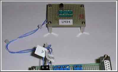
The temperature voltage converter, made with a National Semiconductor LM34 and a National Semiconductor LMC7111 operational amplifier provide the LTD with a voltage proportional to current. Every several seconds, the LTD measured the analog voltage and sends a signal in Morse Code that corresponds to the air temperature. For example, an air temperature of 23.1 degrees centigrade would result in 232 being sent in Morse Code. A block diagram of the demonstration system in shown in Figure 3, and a photograph of it is shown in Photo 2.
A example of how to use the KEY output of the LTD to drive a SAW-based transmitter is shown in figure 4.
Photos 2. The temperature sensor circuit board only requires three conductors to connect to the LTD board -+5 volts, the sensor output, and ground.
For more detail: Digital Telemetry using ATMega8 microcontroller
Digital Telemetry using ATMega8 microcontroller
The ATmega8 microcontroller-based Low-Cost Telemetry Device (LTD) is an efficient telemetry keyer. The LTD measures the voltage levels of up to four analog channels via its on-chip 10-bit ADC, converts the measurements to numbers, and then sends the data in Morse code to an external transmitter and to an attached RS-232 terminal. It can be set up either by the RS-232 terminal, in which case, a character string, such as transmitter ID, can can be sent, or it can be set up with only jumpers to ground. Parts count is very low, in part because the ATMega8’s internal clock is used for timing.Jeff Heidbrier came up with the idea for this project, built the prototype, and colaborated with me on the design of the LTD and this documentation.
Downloads


