Summary of Digital Wall clock Using Atmega-8 and RTC
This article details the construction of a digital wall clock using an Atmega-8 microcontroller and DS-1307 RTC for accurate timekeeping during power failures. The project emphasizes testing on a breadboard before permanent soldering on a perfboard, utilizing shift registers to drive seven-segment displays. It highlights best practices like using IC bases and female headers to prevent component damage and allow future modifications.
Parts used in the Digital Wall Clock:
- Perfboard (about 13CmX10Cm)
- 4x 2.3 inch 7 Segment display
- 4x SN74LS595 8-Bit Shift Registers
- 1x Atmega-8 Microcontroller
- 16 MHz crystal and 2x 22Pf Capacitor
- 7805 voltage regulator
- 5v power supply
- DS-1307 RTC module or IC
- 28x 220 ohm resistors
- 2x 1k and 10k ohm resistors
- 28, 14, 8 pin IC bases
- DC jacks, Male and Female headers, and wire
- Arduino Uno
- Soldering Gun
- Bread Board
- Wire stripper
Clock is one of the most essential house hold things. There are various types of clocks like good old Pendulum clocks, Analog clocks and the now trending modern Digital clocks.
Digital clocks has many advantages over the analog clocks like the Accuracy in time, easy reading of time when compared to analog, visibility even in darkness and so on…
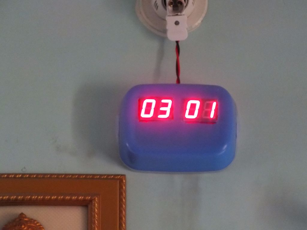
Here a basic Digital Wall clock is presented which is built using simple Atmega-8 microcontroller and DS-1307 RTC which is a time keeper which keeps the time even when there is a power failure.

Digital clocks has many advantages over the analog clocks like the Accuracy in time, easy reading of time when compared to analog, visibility even in darkness and so on…
Here a basic Digital Wall clock is presented which is built using simple Atmega-8 microcontroller and DS-1307 RTC which is a time keeper which keeps the time even when there is a power failure.
Step 1: Tools and materials required.
The components required for the Clock.
Materials:
Materials:
- Perfboard (about 13CmX10Cm)
- 7 Segment display [choose as per the requirement, here 2.3″ display is used]-4
- SN74LS595-8-Bit Shift Registers –4
- Atmega-8 Microcontroller-1
- 16 MHz crystal and 22Pf Capacitor(2)
- 7805 voltage regulator
- 5v power supply(use any mobile charger if available)
- DS-1307 RTC either IC or module
- 220 ohm resistors-28
- 1k, 10k ohm resistor-2
- 28, 14, 8 pin IC bases
- DC jacks, Male and Female headers and some wire
- Arduino uno for testing and uploading the firmware
If RTC module not available:
DS-1307 RTC IC, 32.768MHz Crystal, CR2032 3V Coin cell and Holder, 10K ohm resistors, small Perfboard
Tools:
- Soldering Gun
- Hot Glue Gun (Optional)
- Bread Board for testing the circuit
- Wire stripper
Step 2: Testing!!
Before going to actual soldering process make sure all the components works according to the plan. The simple way to do that is to test it on a Breadboard.
Make all the connections necessary on the bread board and make any changes required in the circuit like brightness of the displays and any updates that should be made to the RTC and so on…
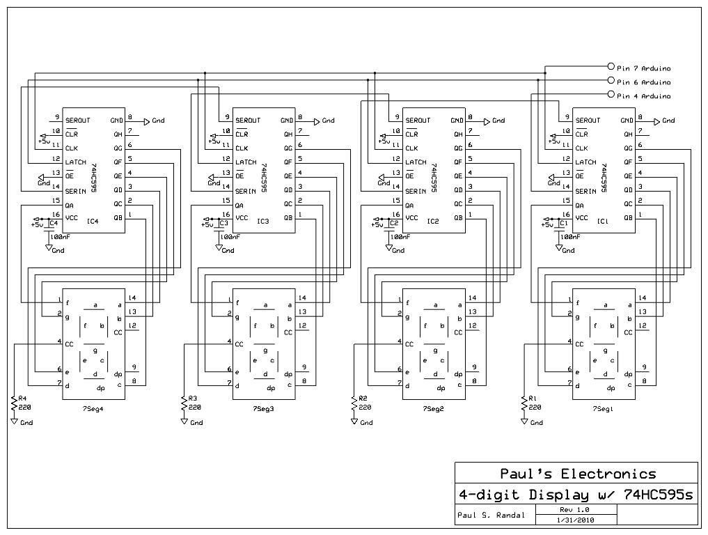
The shift registers are connected in daisy chain array of four which is as shown in the circuit diagram.
The connections of the shift registers are based on information provided in Paul’s electronics web.
For more information on this please visit this link:)
Make all the connections necessary on the bread board and make any changes required in the circuit like brightness of the displays and any updates that should be made to the RTC and so on…
The shift registers are connected in daisy chain array of four which is as shown in the circuit diagram.
The connections of the shift registers are based on information provided in Paul’s electronics web.
For more information on this please visit this link:)
Step 3: Soldering the components on perfboard!!
After the testing is completed and when everything is working fine its time to make the circuit permanent by implementing it on the perfboard or design your PCB layout using various design tools like Eagle and get it fabricated.
The first step in soldering the components is to place them carefully on the perfboard so as to make the connections among the various components easy. Arrange the various components as required and start soldering as per the circuit diagram.
Always use IC bases instead of actual IC’s for soldering on the perfboard. It reduces the risk of burning the IC while soldering and also provides an option to change of an IC in case of damage to it in future.
Use female headers for the 7 Segment displays instead of soldering it directly as you may need to change it in future in case if u don’t like the color of it, or if it gets damaged.
Solder the circuit for the microcontroller and RTC(if module is not available) following the above steps.
Make sure you have loaded the program before placing the Atmega-8 IC in its base.
For more detail: Digital Wall clock Using Atmega-8 and RTC
- Why is the DS-1307 RTC included in this project?
The DS-1307 RTC keeps the time even when there is a power failure. - How should the shift registers be connected?
The shift registers are connected in a daisy chain array of four. - What is the recommended method for protecting ICs during soldering?
You should always use IC bases instead of actual ICs to reduce the risk of burning them. - Why are female headers used for the 7 Segment displays?
Female headers are used so you can change the displays later if you dislike the color or they get damaged. - What tool is required to test the circuit before final assembly?
A Bread Board is used to make connections and test components before soldering. - Can I use a mobile charger for the power supply?
Yes, any available mobile charger can be used as a 5v power supply. - When should the program be loaded onto the microcontroller?
The program must be loaded before placing the Atmega-8 IC in its base. - What alternative components are needed if the RTC module is unavailable?
You will need a DS-1307 RTC IC, 32.768MHz Crystal, CR2032 3V Coin cell and Holder, and a small Perfboard.