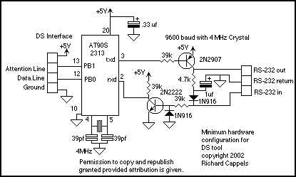
The DS protocol was designed to provide firmware-based bidirectional host-to-slave inter processor communications for situations in which no hardware solution is available and the host and/or the slave in incapable of tending the interface in real time. The only specialized hardware required is two bidirectional I/O ports on each chip (alternatively two input ports and two tri-statable output ports may be used. In other words, it provides some of the functionalit of the Two-Wire-Interface (TWI, or I2C as named by Philips) where an actual TWI is not feasible in either hardware or firmware.
For details of the DS protocol please see this page.
Downloads:
AVR Studio Assembly Source code (HTML -cut and paste into your assemble editor)
AVRStudio hex file
MacAVRPA hex file
Note: Hex files assume 4 Mhz crystal, communications with terminal at 9600 baud, 1 stop bit, no parity.
User map (.PDF file)
Hardware considerations:
The 5 volt power pin on the DS interface may be used to supply power to the DS device being tested. In this case, a power on-off switch would be a good idea. The microcontroller timing is unimportant for the DS device, but it is critical for the baud rate generator on the AT902313. The RS-232 inverters could also be Maxim MAX-232 or something similar. I prefer these discreet inverters because I am building them by hand and they take less board space than the DIP buffers.
On the DS interface side, the firmware provides for week internal pullups on the Attention and Data lines, so no nexternal resistors are required unless there is a large capactive load on these lines, in which casce, resistors as low as 270 Ohms may be used.
Examples of use of the tool.
The test tool provides a means of reading and writing data and commands to a DS slave device and displays data sent from a DS slave as it is received.
=============================================
Coming out of reset, a menu is displayed:
   DS Interface test tool 03 November 2002 Dick Cappels
Space bar = Enter value
M or m = Send value as data
/    = Send value as command
S    = Send value from keyboard to register
D    = Dump registers 0..F
<RETURN> = Print last value buffer
T or t = Set DS port delay parameter
! = reset chip
? = Display menu
All address and values are hexadecimal and are byte wide
Current delay value =  $20 20
:
The colon (:) prompt indicates that a command or daya may be entered. Note that if DS port delay parameter had not been set since the EERPOM was erased, the default will be $FF $FF which is very slow. You might want to adjust the delay parameter. with the T command until the Dump command is fast but reliable.
=============================================
Enter the data value. press the space bar and receive the prompt:
For more detail: DS interface test tool using ATtiny2313 microcontroller

