
Summary of Fully Customized Device On/Off Timer
This article describes a fully customized On/Off Timer project utilizing an ATMega32 AVR Microcontroller. Designed for industrial, domestic, and military applications, the device allows users to switch loads ON or OFF after a set duration between 0 and 9999 seconds. Key features include a simple four-button interface, LCD display, audio notifications via a buzzer, status LEDs, and selectable counting speeds (1 or 10 counts/sec) with up/down direction options. The system operates on a 5V supply and uses a relay to control external devices.
Parts used in the Customized On/Off Timer:
- AVR Microcontroller ATMega32
- Four push buttons
- LCD display
- Green LED
- Red LED
- Buzzer
- Relay (1 C/O type)
- NPN transistors (for relay and buzzer switching)
- 16 MHz crystal oscillator
Timers are used in many different applications for example in Industrial Applications, to switch ON or switch OFF any device or a machine load for a specific period of time. In the same way the timers are used in Domestic Appliances like in Air Conditioners, Microwave Ovens, Washing Machines, Food Processors etc.
The applications for the timers could also be seen in Military Applications and Space Applications, to trigger any Bomb or a Missile or to ignite booster rockets for lift offs at a specific time.
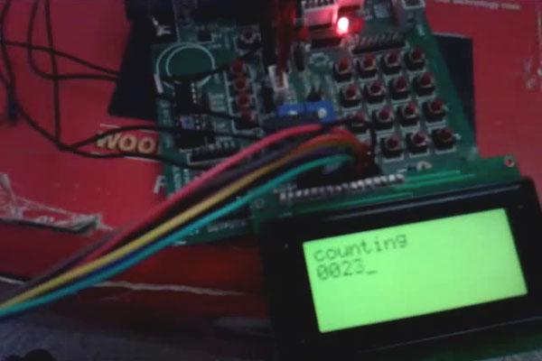
Here the given project demonstrates the fully featured and customized timer built using AVR Microcontroller ATMega32.
Features of the On/Off Timer
· Simple user interface using only 4 push buttons
· LCD for message display
· LEDs for indications
· Buzzer for audio notification
· Can count from 0 to 9999
· User selectable two counting speeds – 1 count/sec and 10 count/sec
· User selectable count up or count down
· Potential free (relay) contacts for device/machine/load on/off
User can connect any device or machine with the timer relay contacts. Set the desire count from 0 to 9999. Set counting direction either up or down and set counting speed either 1 count/sec or 10count/sec. Then when he press start switch to start timer operation, the device/machine will remain ON till the count finishes. As the count finishes, the device will shift to OFF mode and a beep sound is produced for audio notification. The whole counting process is displayed on LCD as count increments of(or) decrements. Two LEDs – one green and one red, are also given for indication of counting process.
Circuit Description
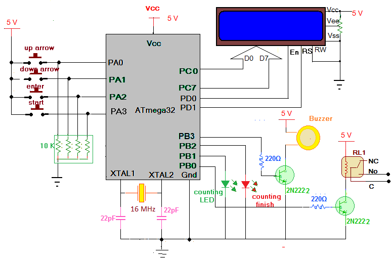
The complete circuit is built around AVR Microcontroller ATMega32. It consists of push buttons for user setting,LCD display, LEDs for indication, buzzer for audio notification and relay to switch on/off load or device. For complete Circuit Diagram click on the Circuit Diagram Tab.
· Four push buttons are connected to PORTA pins PA0 – PA3 such that when button is pressed that pin will get momentarily high logic input
· PORTC is connected to data pins D0 – D7 of LCD that sends command or data to LCD
· Two control pins En and Rs of LCD are connected to PORTD pins PD0 and PD1 respectively. Third control pin RW is connected to ground to make LCD write always enable
· PB0 pin drives 1 C/O (change over) type relay through NPN transistor connected in switch configuration
· Similarly PB3 pin drives DC buzzer through another NPN transistor connected in switch configuration
· One green and one red LEDs are connected to PB1 and PB2 pins to indicate counting process is going on or finished
· A 16 MHz crystal is connected to crystal input pins to provide internal clock for operation
· Complete circuit works on 5 V supply
For more detail: Fully Customized Device On/Off Timer
-
What is the maximum count value supported by the timer?
The timer can count from 0 to 9999. -
How many push buttons are used for the user interface?
The project uses only 4 push buttons connected to PORTA pins PA0 through PA3. -
Can the user select different counting speeds?
Yes, the user can select between 1 count per second and 10 counts per second. -
Does the device support both counting up and counting down modes?
Yes, the user can select either count up or count down directions. -
What provides audio notification when the timer finishes?
A buzzer produces a beep sound when the count finishes. -
How is the load or device switched ON and OFF?
A potential free relay controlled by a transistor switches the device or machine load. -
What voltage does the complete circuit operate on?
The entire circuit works on a 5 V supply. -
Which microcontroller is used as the core of this project?
The project is built around the AVR Microcontroller ATMega32.
