Summary
We used two stepper motors to drive a steel ball scavenged from a ball-bearing. These motors were controlled by a PS/2 mouse wirelessly using the RCR-433 and RCT-433 receiver/transmission combination mentioned in lecture. We then took the PS/2 protocol, made it compact, modified existing transmission code and deduced a way to control the robot via the mouse. We also mounted a solenoid which raises and lowers a writing instrument. The device is meant to write on a sheet of paper.
By using a mouse to control the robot, anyone can sit down and doodle remotely with it. This was done since we wanted to create a project that could be used intuitively by anyone and be fun, yet useful in some applications. Also, we wanted to build a robot since robots are interesting. We chose the spherical drive since it was a novel approach that we had only seen a few times on the internet (http://www.ri.cmu.edu/pubs/pub_5457.html). We made the design wireless to allow the robot to move unopposed in any direction.
High Level Design
Rationale
We were trying to figure out what to do for our final project when we came across the idea of creating something we could entertain and scare people with. After some research online we were determined to make the ghost writing robot. We wanted to be able to put the robot in a room and from another room get it to draw messages and images wirelessly. We also wanted to create a system for easily blowing up or shrinking what someone draws while maintaining accurate drawing scale.
We chose the spherical drive train since that most accurately mimics the mouse movements and would allow for drawings that did not have unnecessary curves due to rotation of a conventional drive train (like 2 or 4 drive motors controlling wheels that are parallel to each other). In determining the motors to use, we chose stepper motors since they were small in size yet had a sizeable amount of torque, which we felt would be necessary for driving the robot, the electronics, and batteries. By using this drive train we also simplified the amount of software needed to translate the mouse input into stepper motor control since both would now be on a similar Δx and Δy coordinate system.
Background Math
Most of the mathematics behind this project dealt with timing. The mouse defaults to 100 packet updates per second. However, we found that with a maximum baud rate of 4800, the wireless link can only send 480 bytes per second, or at most 160 mouse packets. Additionally, running the wireless at maximum speed caused a couple of dropped packets, whereas running it at around 4300 baud provided near flawless communication; so we did. With the overhead on the packets however, we were only able to transmit 4300/10 = 430/15 = about 27 mouse packets per second. We reduced the overhead on the wireless link and were able to transmit 430/5 = 86 packets per second. Since the mouse can only deal with certain discrete values, we had to settle for 80 updates per second, which is more than enough to report apparently smooth motion.
The motors also have timing issues. Assuming 80 updates occur per second, one update reaches the receiver every 12.5 ms. The limit on the motors (tested by trial and error) seemed to be about one update (motor tick) every 2 ms. Additionally, we switched to a half-step drive for the motors, which cuts the max speed to one half motor tick per 2 ms, one full tick per 4 ms. Therefore, the mouse would theoretically only be able to move 3 spaces per update, or ¾ mm. (One unit of mouse movement = ¼ mm, although this can be changed by sending a command to the mouse.) ¾ mm per 12.5 ms = 60 mm per second, or about 2.5 inches per second. We figured that this would be ok, since we don’t really want the robot to be made to move too fast anyway, and we essentially buffer anything beyond this limit using the xmov and ymov variables in rx.c. The timing we ended up going with was 313 overflows of timer 0, or 313 * 16 us = 5 ms per half tick. We find that as long as the mouse is moved fairly slowly (which is pretty essential if you want to draw accurately with the mouse), this causes no overflow problems with the motors.
Each unit of mouse movement translates to one half tick of the motor. Theoretically, this means that each ¼ mm of mouse movement translates to pi * ¾ in = roughly .6 mm after unit conversions. This would mean that given a perfect drivetrain the drawing would be scaled up. However, given the slippage of the ball, the drawing comes out to be much closer in size to the mouse movement. We actually wanted to keep the drawings small for the safety of the robot and for simplicity’s sake, so this works out.
Logical Structure
The high level structure follows a simple scheme of taking input from the PS/2 mouse, sending it wirelessly from one Atmega32 to the Atmega32 onboard the robot and then driving the motors and solenoid. It is illustrated in the following diagram.

Hardware/software tradeoffs
In the creation of the robot, we ended up hitting quite a few snags due to physical, as well as hardware, limitations. Of these were speed of the motors—if the motors ran too fast they slipped on the sphere and the robot would just jerk and not move. In order to account for this, in software we slowed down the maximum operating speed of the stepper motors. We also had to sacrifice accuracy of the robot due to inability of the design to drive the sphere straight in the cardinal directions (+,-x and +,-y). The limitations of the wireless transmitter and receiver meant that we had to eliminate bytes of overhead from the transmission as well as package the PS/2 mouse output to take up less room in order to increase the data rate from the mouse. This is evident in that initially the 100 updates/second from the mouse was producing a massive amount of packet loss due to wireless overhead constraints. By reducing the updates/second to 20 and gradually increasing it from 20 to 80 while removing a lot of overhead bytes (as discussed in the software section), we were able to get smooth updates from the mouse. The goal was for the mouse to be the limiting factor in precision for the project, not the wireless or the robot.
Standards
Our robot’s wireless transmitter and receiver combination complies with FCC standards since it does not interfere with licensed transmitters and it transmits in the acceptable range of frequencies found in Part 15 of the FCC rules (http://www.access.gpo.gov/nara/cfr/waisidx_01/47cfr15_01.html).
Since we used a PS/2 mouse we had to develop a way of conforming to the PS/2 mouse protocol (http://www.computer-engineering.org/ps2protocol/). We also used a 6-pin mini-DIN connector as per required by the PS/2 protocol. Due to this, any mouse that complies with the standard can be used with our project.
Patents, Copyright, Trademarks
Since we used the PS/2 mouse protocol (somewhat reversed engineered), it should be acknowledged that the full protocol was developed by IBM. We have not used any other patented or potentially patented hardware or software in the design of this project. Our code has been modified from other code released under the GNU Public License and the authors have been acknowledged in this report.
Program/Hardware Design
Software Details
PS/2 Interface
The interface to the PS/2 mouse is located on the transmitter chip and in tx.c. The PS/2 protocol allows 2-way communication with a keyboard or mouse using only 2 electrical lines, data and clock. Both lines are defaulted to high but can be pulled low by either the host (the microcontroller) or the device (the mouse). Communication with the mouse is initiated when the MCU pulls the clock low (inhibiting mouse communication to the MCU), then sends a 0 over the data line, then releases control of the clock back to the mouse. The mouse then sends a clock signal allowing the host to send a data packet. First a start bit (0) is sent, then 8 data bits, then an odd parity bit, and finally a stop bit (1). The mouse then sends an acknowledgement bit (0) and will follow that up with its own communication. When the mouse communicates to the host, it drives the clock line itself and sends data in the same format as described above. The send() function allows for host-to-mouse communication, while mouse-to-host communication is triggered by an external interrupt (using PORTD.2) that fires when the start bit is sent from the mouse. The other functions used are init_receive() and disable_receive(), which turn that external interrupt on and off. In order for the MCU to send a command to the mouse, it must first turn receiving off in order to prevent that interrupt from firing.
To set up the mouse for our purposes, we first send a reset command (0xff) to verify that the mouse is connected properly and is working. We then send 0xf3 followed by a decimal number to set the mouse sampling rate. This number can be 10, 20, 40, 60, 80, 100, or 200, and represents the number of mouse updates per second (we use 80, as it is the fastest we can go without exceeding the baud rate of the wireless transmitter). Finally, a 0xf4 command is sent to enable mouse data reporting, and the mouse will then send updates in the form of packets.
Wireless Link
The wireless code is present on both chips, and also in txrx.c, a header file originally written by Meghan Desai that provided a protocol for wireless transmission. Due to the timing issues described above, however, the protocol had to be modified somewhat. We attempted to cut back as much overhead as possible from the packets and were able to reduce amount of overhead from 12 bytes to 1 byte, which brought the allowable sampling rate of the mouse from 20 packets/second to 80 packets/second. Our wireless uses the same functions as the original code, but only sends 1 byte of 0xaa for calibration/synchronization of the two units (we tried getting rid of this too, but it wouldn’t work). In addition, the start byte is now compressed with part of the mouse data; the first half of the start byte is overhead, and the second half contains the mouse button info and sign bits for the movement. (The overflow bits are barely physically relevant, since the user would have to move the mouse about 3 inches in 12.5 ms, or about 20 feet per second, to cause an overflow; the robot itself can’t handle this as it is. The middle mouse button is not present on the mouse, and the “Always On” bit is, well, always on, and thus does not need to be sent.) The last two bytes contain the X and Y movement, respectively. Packet length for our purposes is always 3 (4 including overhead), so there is no need for an end byte or transmitting the length of the packet. Channel ID’s, while originally present, do nothing to prevent physical collisions of packets, so they were removed as well. While the encoding scheme used by Meghan Desai is useful for reliability, we found that without it, our link rarely if ever dropped a packet, and since higher sampling rate was of greater priority, we discarded it.
When a packet is ready to transmit, the USART is first cleared with 0x00, then the packet is sent using the tx_me() function. This function will place the mouse packet into a transmittable packet (with a synch byte and “start nibble”) and send it using the UDR Empty interrupt. The interrupt had to be modified to continuously clear the USART whenever a packet was not being transmitted.
On the receive side, a packet comes in and is decoded using the RXC interrupt (RX complete). When a packet is fully received, rx_done() is set, and the necessary data is extrapolated from the packet.
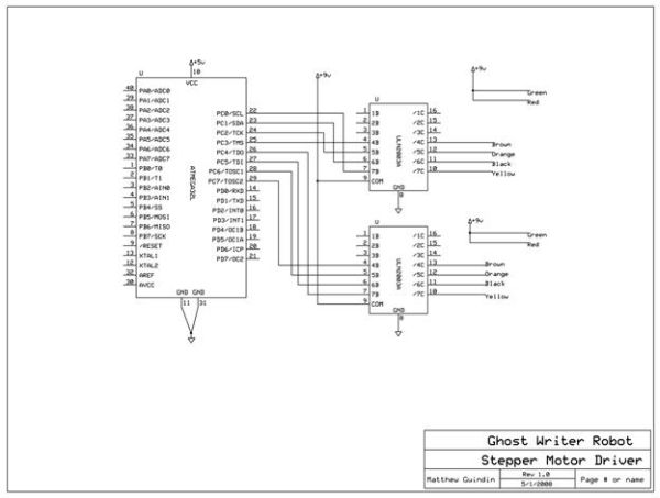
Motor Control
The two stepper motors are controlled using 4 wires that go to 2 coils. Essentially, to control a stepper motor, one must first power one wire, then the next, then the next, etc. (i.e. send 1000, 0100, 0010, 0001, 1000, 0100, and so on, to make the motor move). In order to produce more torque out of the motors, we used a “half-stepping” method of driving (send 1000, 1100, 0100, 0110, 0010, 0011, 0001, 1001, and repeat). Although half stepping effectively halves the top speed of the motors (the motors we used cannot handle signal changes quicker than one every 2 ms or so), this proved irrelevant, since the robot itself refused to move at speeds that fast. We had to drive the motors at a speed that would be slow enough to drive the robot without tons of slipping yet would be quick enough to preserve the accuracy of the drawing.
The motor is controlled by task1 on the receiver chip (rx.c) which is scheduled by Timer 0. When Timer 0 overflows, a virtual timer is decremented. When the timer hits 0, the motors’ positions are updated based on the values of xmov and ymov, two variables that accumulate based on the data packets that come in.
Solenoid Control
The solenoid is controlled by the left mouse button. It is wired to be active low: it raises the pen when the port pin (D.3) is set high, lowers it when the pin is set low. To do this, it takes the last bit from the first data byte whenever a packet is received by the MCU mounted on the robot.
Hardware Details
The hardware for the project was mostly borrowed from previous projects and then modified to suit our needs. However, this was not just a straight-forward task as the circuits provided on some project pages had key elements poorly labeled or missing and thus we had to research how these circuit exactly worked to implement them correctly.
Parts List:
Cost Details
STK500: $15
DIP socket(2): $1
Atmega32 : 8 = $8
Atmega32 (second): Sampled, Atmel
RCT-433 Transmitter: $4
RCR-433 Reciever: $4
Max233: $7
Power supply: $5
custom PC board: $5
Stepper motor (2) (35T-48):: $2
GUARDIAN A420-067074 Solenoid: $3.85 (All Electronics)
PS/2 connector: $1
PS/2 mouse: Free (old mouse)
Steel ball: Free (scavenged from old bearing)
Aluminum: $1 (1/12 of $12 piece)
Lexan: free (found in machine shop)
Screws & nuts: free (found in house)
Grommets: free (found in machine shop)
Battery(4): $8
Small solder board (4): $4
Assorted capacitors, inductors, LEDs, and resistors: free (from lab)
2N3904 (3): Free (from lab)
TIP31: Free (from lab)
ULN2003AN (2): Free (from lab)
9V connectors (3): Free (from lab)
Cable ties: Free (Matt purchased before Spring 2007)
Pen/Sharpie: Free (found around house)
Epoxy: Free (from machine shop)
Total: $68.85
For more detail: Ghost Writing Robot Using Atmega32