Summary of Goldilocks Analogue – Prototyping 3
This article details the third prototype of the Goldilocks Analogue synthesizer, focusing on a strategic shift to enhance performance. The author completed the PCB layout for the fourth prototype and began testing new SPI EEPROM and SRAM capabilities alongside an MSPIM interface for the DAC. A key revision involves moving the MCP4822 DAC from standard SPI pins to USART1 in Master SPI mode using an ATmega1284p microcontroller. This change allows for higher throughput and avoids conflicts with the slow SD card, while maintaining compatibility with the Gameduino2 LCD and touch screen.
Parts used in the Goldilocks Analogue:
- Goldilocks Analogue 3rd Prototype
- ATmega1284p microcontroller
- MCP4822 DAC
- SPI EEPROM
- SRAM
- Gameduino2 LCD
- Touch screen
- SD card
- FRAM
- NASA EEFS simple flash file system
Following my initial design article, and the follow up design article, I’ve put quite a lot of thought into how I can make this Goldilocks Analogue device best achieve my stated goals. Pictured is the new 3rd Goldilocks Analogue Prototype.
I’m now working on the 4th Goldilocks Analogue Prototype. The PCB layout has been completed, and we’re talking about how to produce it with a view that this will become the final and possibly production version.
The finished 3rd Prototype boards are now in my hands, and testing of the PCB configuration the new SPI EEPROM and SRAM capabilities, together with MSPIM interface for the DAC begins. These two features contribute to making the Goldilocks Analogue great analogue synthesiser platform. Combined with a Gameduino2 LCD and touch screen, it creates flexible sound touch controller, with quality analogue stereo output.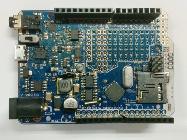 This is the working design document. It will grow as I get more stuff done, and notes added here. I’ve pretty much finished the paper design now, and will let it settle for a few weeks over the 2014 holiday season. It is sometimes good to do things again, with a few weeks perspective from the original decisions.
Major Revision in Strategy
Over the past months I’ve been spending time writing code to go along with the latest revision of the Goldilocks Analogue. I have successfully implemented a version of the NASA EEFS simple flash file system, to use to buffer data either for acquisition or for analogue playback, and I’ve been working on streaming functions to get data off the SD card and off the EEFS flash file system. The outcome is that it is not possible to do everything with just one SPI bus, and keep generality when needed. The SD card is just too slow, and can’t be easily interrupted. The FRAM/SRAM/EEPROM doesn’t have enough storage to effectively stream GigaBytes of data, as a uSD card can achieve.
So, what to do? Adafruit uses a software bit-banged SPI outcome to drive their MCP4921 and doesn’t get close to the maximum speed I want to achieve. Fortunately, with the ATmega1284p there is a simple answer at hand. I have decided to move the MCP4822 off the standard SPI pins, and connect it to the USART1 TX and XCK pins, using the USART in its Master SPI mode.
This is a major revision in strategy. Previously I have been very adverse to putting anything on the standard Arduino pins, preferring to keep all of the Goldilocks extra features off the Arduino footprint. However, the outcome is well worth using the USART1 to drive the MCP4822, and nothing is compromised.
USART MSPI mode is available on any ATmega device. On the UNO platform, using the ATmega328p, there is only one USART and so of course it is reserved for serial communications. The Goldilocks ATmega1284p has two USART interfaces, and usually the second one (USART 1) goes unused. Therefore connecting its XCK and TX pins to the MCP4822 is the simplest and best outcome to achieve high throughput and regularity SPI output on a non-shared SPI interface. And, as the MCP4822 DAC has high impedence (~10kOhm) inputs, having the DAC sharing the pins won’t affect normal pin usage to any extent.
And, there’s more win. The USART MSPI has double buffering for the transmit function. This means that we can actually achieve a higher throughput using the USART MSPI than we can using the standard SPI bus! These logic traces demonstrate that the my best implementation of the SPI interface requires 4.58us to transmit a “frame” of information, consisting of two 12 bit samples. Using the USART MSPI interface we can achieve 4.25us per frame.
For more detail: Goldilocks Analogue – Prototyping 3
- What is the main goal of the Goldilocks Analogue project?
To create a great analogue synthesiser platform with flexible sound touch controller capabilities. - Can the SD card handle all data streaming needs alone?
No, the SD card is too slow and cannot be easily interrupted, making it insufficient for everything. - How does the author drive the MCP4822 DAC in this design?
The DAC is connected to the USART1 TX and XCK pins using the USART in its Master SPI mode. - Does using USART1 for the DAC affect normal pin usage?
No, because the MCP4822 DAC has high impedance inputs, sharing the pins does not affect normal usage. - Why was the strategy changed regarding the SPI bus?
A single SPI bus could not support both the slow SD card and the required generality for other features. - What advantage does the USART MSPI mode offer over standard SPI?
It provides double buffering for the transmit function, achieving higher throughput than the standard SPI bus. - How long does it take to transmit a frame using the best SPI implementation?
It requires 4.58us to transmit a frame consisting of two 12 bit samples. - How much time does the USART MSPI interface save per frame?
It achieves 4.25us per frame, which is faster than the standard SPI implementation. - Which microcontroller is used in the Goldilocks Analogue 3rd Prototype?
The design uses the ATmega1284p microcontroller which has two USART interfaces. - What happens if you try to use the UNO platform for this specific configuration?
The UNO platform only has one USART reserved for serial communications, leaving no room for this setup.