
Summary of InLinea01: A PID controlled line following robot build on an ATmega 8
This article describes InLinea01, a prototype PID-controlled line-following robot designed to track lines on the floor using reflective sensors. The system utilizes an ATmega8 microcontroller for logic, driven by two DC motors controlled via an L9110S H-bridge. It employs eight TCRT5000 sensors for detection and uses an LM2596S converter and LM7805 regulator for power management from a 7.4V LiPo battery. The PID parameters are adjustable via UART with a Bluetooth HC-05 adapter, allowing wireless tuning without physical cables.
Parts used in the InLinea01:
- ATmega8 microcontroller
- Two 200rpm @ 6v DC motors
- L9110S H-bridge based controller board
- Eight TCRT5000 reflective sensors
- HC-05 bluetooth adapter
- 7.4v LiPo battery
- LM2596S DC/DC converter
- LM7805 voltage regulator
InLinea01 is a simple PID controlled line following robot.
This is not speed oriented line follower, this is just a prototype I built to experiment with this type or machines, though it can be the first step to build a faster one.

The goal of a line following robot is follow a line that is draw on the floor, usually this line is a black on white floor line, or a white on black one.
A sensor is needed to detect the line, and mantain the robot over the line.
This follower has two 200rpm @ 6v DC motors, driven by a L9110S H-bridge based controller board.
Detector is build using 8 cheap TCRT5000 reflective sensors. It can detect black on white, or white on black lines. The dection inversion must be decided at compile time.
It uses PID controller to make the robot follow the line smoother.
The PID parameters can be setup via UART using a GUI, the UART connection can be estabilished through a bluetooth adapter like the HC-05, if you use this type of connection, you can setup PID variables leaving cables out of the robot. That’s pretty usefull for a line following robot.
The core of the robot is a ATmega8 microcontroller running at 8Mhz with his internal crystal.
A 7.4v LiPo battery powers the robot. Then an LM2596S based DC/DC converter regulated to 6v feed the 2 motors, and a LM7805 voltage regulator all other components.
In a few words, sensor detect the line. In order for the robot to follow the line, it has to be centered over it. To keep the robot in the middle of the line the speed of eveny wheel must be changed. The difference in speed of rotation determines the robot direction. That speed is evaluated by the PID controller depending on the position error.
As example, if the line is detected by the right detectors, then left motor has to spin less than the right one, that way the robot will turn a little on the left, and the line will be again in the center position.
The PID controller prevents robot oscillations and smooth his path.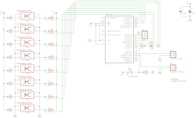
For more detail: InLinea01: A PID controlled line following robot build on an ATmega 8
-
What is the primary function of the InLinea01 robot?
The goal is to follow a line drawn on the floor, usually black on white or white on black, while maintaining its position over it. -
How does the robot detect the line?
A detector built using eight cheap TCRT5000 reflective sensors is used to detect the line color contrast. -
Can the sensor detection inversion be changed dynamically?
No, the detection inversion must be decided at compile time. -
How are PID parameters configured for this robot?
PID parameters can be set up via UART using a GUI connected through a Bluetooth adapter like the HC-05. -
What happens if the line is detected by the right detectors?
The left motor spins less than the right one, causing the robot to turn slightly left to center the line again. -
What component powers the motors and what voltage do they run at?
A 7.4v LiPo battery powers the robot, and an LM2596S based DC/DC converter regulates power to 6v for the motors. -
Why is a PID controller used in this project?
The PID controller prevents robot oscillations and smooths the path by evaluating speed differences based on position error.
