Summary of How to interface LCD in 4 bit mode with AVR microcontroller
This article details interfacing an LCD with an ATmega16 microcontroller using 4-bit mode to conserve pins. It explains that data is sent in nibbles, starting with the higher nibble, and describes the initialization process involving specific hexadecimal function set commands (0x20 and 0x28) to configure the display for 2 lines and 5x7 dots. The text outlines circuit connections where LCD data lines link to PORTA and provides C code for initialization and bit manipulation logic.
Parts used in the LCD Interfacing Project:
- ATmega16 Microcontroller
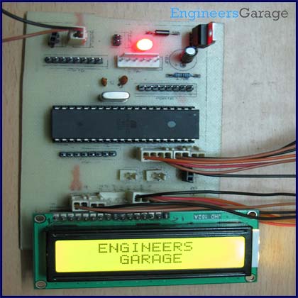
- HD44780 LCD Module
- Data Lines (D4-D7)
- RS Pin
- RW Pin
- EN Pin
- PORTA Pins (PA4-PA7)
This article explains interfacing of LCD with ATmega16 using 4-bit mode. In this mode only four pins are used for sending data and command instructions. This mode has the advantage over the 8-bit mode as it uses less number of pins. The remaining pins of the controller are available for normal use.
The Data or command is sent in nibble form (1 nibble= 4 bit) in the 4-bit mode. The higher nibble is sent first followed by the lower nibble. The function of RS, RW and EN pins remains similar to 8-bit mode.
Circuit description:
Connections of LCD with ATmega16 are shown in circuit diagram. In 4-bit mode, the Data lines must be connected with D4, D5, D6 and D7 pins of LCD module.
Initialization:
The LCD can be configured in 4-bit mode by sending appropriate instruction which is called “Function set” to it. The Function set is hexadecimal instruction for LCD MPU unit, which selects working modes of LCD. The “Function Set” is mentioned in following table:
Description:
DL – Data Length (DL = 1 8bit, DL = 0 4bit)
N – No. of Lines (N = 1 2Lines, N = 0 1Lines)
F – Fonts (F = 1 5×10 dots, F = 0 5×7 dots)
According to table, the value of Function Set for 4 –bit mode will be 0010 0000(0x20) because DL=0. The value “Function Set” for the LCD configuration 2 line (N=1), 5X7 dots (F=0) and 4-bit (DL=0) mode will be 0010 1000(0x28).
When the power supply is given to LCD, it remains in 8-bit mode. Now, if 0x20 is sent, lower nibble will not be received by LCD because four data lines (D4-D7) are connected, so 0x02 is sent instead of 0x20.
Programming Steps:
Step1: Initialization of 4-bit mode.
void lcd_init() // fuction for intialize
{
dis_cmd(0x02); // to initialize LCD in 4-bit mode.
dis_cmd(0x28); //to initialize LCD in 2 lines, 5X7 dots and 4bit mode.
dis_cmd(0x0C);
dis_cmd(0x06);
dis_cmd(0x83);
}
Other instructions like clear LCD, cursor on etc. are same as mentioned in previous article. Readers can refer datasheet of HD44780 LCD datasheet.
Step2: Nibble arrangement.
Higher pins of PORTA (PA4-PA7) are connected to data line. So, the higher nibble of a byte can be sent to LCD data lines by masking lower nibble. To send lower nibble, data byte is shifted left for four places. Lower nibble replaces higher nibble by this shifting. Data is sent after masking the byte.
For more detail: How to interface LCD in 4 bit mode with AVR microcontroller
- How many pins are used for data in 4-bit mode?
Only four pins are used for sending data and command instructions. - What is the advantage of 4-bit mode over 8-bit mode?
It uses fewer pins, leaving the remaining controller pins available for normal use. - In what order are nibbles sent during data transmission?
The higher nibble is sent first followed by the lower nibble. - What hexadecimal value initializes the LCD in 4-bit mode?
The value 0x20 is sent to initialize the LCD in 4-bit mode. - What is the Function Set value for a 2-line, 5x7 dot, 4-bit configuration?
The value is 0x28. - Which ports connect to the LCD data lines in this project?
The higher pins of PORTA (PA4-PA7) are connected to the data lines. - How is the lower nibble prepared before sending it to the LCD?
The data byte is shifted left for four places so the lower nibble replaces the higher nibble. - What happens if 0x20 is sent when only D4-D7 are connected?
The lower nibble is not received, so 0x02 is sent instead of 0x20.