Summary of LCD DATE TIME TEMPERATURE AT89C52 DS18B20 DS1302
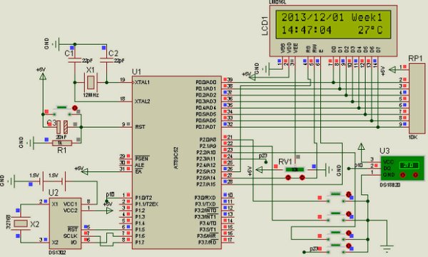
This article describes an AT89C52-based temperature meter project integrating a DS1302 real-time clock, DS18B20 temperature sensor, and a 2×16 LCD. The system uses four buttons for time setting: the first button initiates long-hold mode to set hours, followed by minutes and seconds via subsequent buttons, with settings saved after the final hold. The microcontroller operates at 12MHz, and Keil source code along with Proteus simulation files are available for download.
Parts used in the AT89C52 Temperature Meter Project:
- AT89C52 Microcontroller
- DS18B20 Temperature Sensor
- DS1302 Real-Time Clock Module
- 2 × 16 LCD Display
- 4 Push Buttons
- 12MHz Crystal Oscillator
Atmel microcontrollers with a good example for the use of DS18B20 DS1302 circuit 2 × 16 LCD display with 4 buttons in circuit adjustments can be made The first button is a long hold… Electronics Projects, LCD Date Time Temperature AT89C52 DS18B20 DS1302 “8051 example, avr project, keil example, microcontroller projects, “
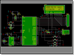
Atmel microcontrollers with a good example for the use of DS18B20 DS1302 circuit 2 × 16 LCD display with 4 buttons in circuit adjustments can be made
The first button is a long hold in seconds (h) setting switches to the second and third button with the settings is done after the first operation are repeating minutes goes like this continue operations after the last button and holding the set is being stored Retrieving AT89C52 system 12MHz frequency works
AT89C52 TEMPERATURE METER PROJECT
Temperature AT89C52 keil source code proteus isis simulation schematic files download: lcd-date-time-temperature-at89c52-ds18b20-ds1302.rar
- How do you set the time on this circuit?
The first button is held long to enter hour setting mode, then the second and third buttons adjust minutes and seconds respectively, with the final hold saving the settings. - What frequency does the AT89C52 system operate at?
The system works with a 12MHz frequency. - Which microcontroller is used in this example?
The project uses an Atmel AT89C52 microcontroller. - What sensors are included in the circuit?
The circuit includes a DS18B20 temperature sensor and a DS1302 real-time clock module. - Can I simulate this project before building it?
Yes, Keil source code and Proteus ISIS simulation schematic files are available for download. - How many buttons are used for adjustments?
Four buttons are used in the circuit for adjustments. - What display type is used in the project?
A 2 × 16 LCD display is used to show date, time, and temperature. - Where can I find the source code for this project?
The source code and simulation files can be downloaded as lcd-date-time-temperature-at89c52-ds18b20-ds1302.rar.