As most guys I don’t tell my wife that “I love you” as often as I should, but this little gadget will at least improve that situation as bit.
So by combining a nice box and some hardcore electronics nerdiness I’ve made a nice christmas gift for my wife. The LoveBox is a small box that when opened displays a random message of love to the viewer.
Step 1 Alternative usages
For gamblers the box could be adapted to show lotto numbers when opened.
The possibilities are endless as most people needs to be told something or make decisions….
Step 2 What you need
- A nice box
- A alphanumeric display
- A microcontroller
- A 74HTC138 (3-to-8 decoder)
- Some resistors
- Two 3-volt batteries
- A microswitch (NC)
- Wires, hot glue gun, soldering iron and other small tools.
In this project I used a box that I stole from my wife, an eight character 14-segment display I got of eBay a year ago, a AVR ATtiny2313 micorcontroller and two 3-volt lithium batteries for cameras.
Step 3 Schematics & Software
Schematics
The schematics for this projects is rather simple.
There’s the microcontroller , the digit “driver” and the display and some resistors to limit the current between the microcontroller and the display.
There are 14 anodes (positive)on the display, one for each segment on a digit, and 8 cathodes (negative), one for each digit.
The anodes are connected to 14 of the available ports on the microcontroller via 330 ohm resistors to reduce the current to a level that the display is not harmed by. U/R=I , that is Voltage divided by Resistance gives Current. The power supply is 6 volts and the display itself it dropping that by 1.8 volt so the resistor of 330 ohm will have 4.2 volts left to take care of. 4.8/330=0.012 (12 mA).
The datasheet for the displays says 2 mA per segment, and I choose to interpret that as as average figure. Since only one digit is lit at the same time each digit will only be lit for 1/8 of the total time. So to get 2 mA of average current is can be driven by 16 mA (2 mA times 8).
Even if this is not according to specs there are both safety margins and the display is only used intermittently and it if should break – who really cares? 😉
The 74HTC138 that drives the anodes is really abused. If all segments on a digit is lit all of the 14 segment want to force 12 mA down through the poor ‘138. This would be a total current of 168 mA and that’s far far far beyond what it can handle to sink.
Depending on the exact model of the chip the specified sink current is more like 5-10 mA. If I short circuit the output and measure it it can sink about 40 mA with an increased voltage level.
Now, all of the segments won’t be lit at the same time, but the 40 mA limit will be reached quite often. Luckily enough the brightness of the display is rather constant whether it gets 4 mA or 15 mA, so it really doesn’t matter that much.
It works, but it’s a really sloppy and unprofessional design. It can be much better, but since I didn’t have any better parts at hand I just used whats worked.
Software
The software is also really simple.
When the microcontroller starts is will read a seed for the random number generator from the non-volatile eeprom of it’s memory, generate a new random number and then write back the new seed to the eeprom. Without keeping track of the seed that random number generator would generate the same number for each start. Hardly not any randomness in that 😉
It then takes the generated random number and uses that for selecting one of several messages and scrolls that past the display.
When the entire message is displayed the microcontroller shuts itself down to a low power mode in order to save the batteries from draining too quickly if the lid inadvertently is left open.
Step 4 Building it
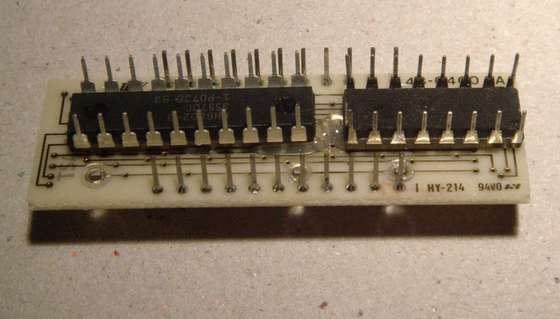
The pictures here shows a few steps of the soldering process.
If it looks really tight and messy it because it’s is really tight and messy! I soldered a few of the resistors in the wrong position and decided to fix those errors by some extra bit fiddling on the software rather than staring to desolder and reconnect it in this mess… Do what’s simplest, it’s not like anybody will notice it anyway. 🙂

