
Summary of PORTABLE RF JAMMER CIRCUIT ATMEGA48
This article describes a compact, portable RF jammer circuit designed around the ATmega48 microcontroller. It features a three-layer PCB capable of 1W high-band and 3W low-band output power. The system utilizes a 3.7V battery with a DC-DC converter for voltage regulation and includes components like ROS2500, ROS1200, SXE-389, LM358, and AD8402. The author warns that jammers suppress original signals and are illegal to use, noting that the provided source code and PCB designs may require adjustments for specific PLL operations.
Parts used in the Portable RF Jammer Circuit:
- ATmega48 microcontroller
- ROS2500 component
- ROS1200 component
- SXE-389 component
- LM358 operational amplifier
- AD8402 component
- DC-DC integrated voltage converter
- 3.7V mobile phone battery
- Three-layer printed circuit board (PCB)
So far I have ever seen , tidy and with all the resources shared jammer circuit project design, it’s very smart Sizes also pretty small pocket on the internet a lot jammer circuit ,… Electronics Projects, Portable RF Jammer Circuit ATmega48 “avr project, microcontroller projects, “
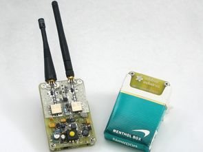
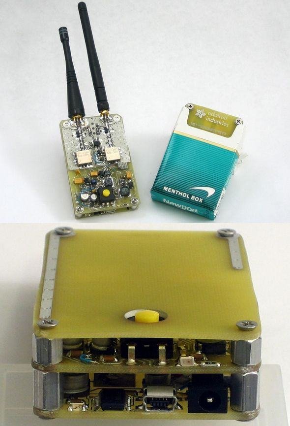
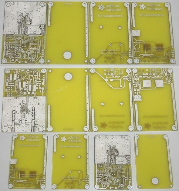
So far I have ever seen , tidy and with all the resources shared jammer circuit project design, it’s very smart Sizes also pretty small pocket on the internet a lot jammer circuit , however, this circuit more like simple but integrates most of us in our market does … Circuit of the printed circuit board 3 floor consists of output power in the 1watt high band , low band 3watt
Jammer circuit mobile phone battery with 3.7v supply provided with integrated voltage converter dcdc used in raising the necessary parts . Jammer on the ATMEGA48 microcontroller , ROS2500 , ROS1200 , SXE- 389, LM358 , etc. ad8402 . abundance outside the integrated voltage regulator and converter used dcdc
CAUTION Jammer frequency to a frequency of the same value , is a device to signal that suppresses the original signal . jammer is forbidden to use this project to share the purpose of source code and PCB drawings is that the different projects, the PLLs , high frequency for operations such as C code may work influenced, may also RF PCBs in designing resource eagle pcb design would be helpful
Source: ladyada.net/make/wavebubble/index.html alternative link: portable-rf-jammer-circuit-atmega48.raralternative link2 alternative link3 alternative link4
Read More Information….
- What is the power output of this jammer circuit?
The circuit provides 1 watt for the high band and 3 watts for the low band. - Can I use a standard battery for this project?
Yes, it uses a 3.7V mobile phone battery supplied with an integrated DC-DC voltage converter. - Which microcontroller is used in this design?
The project integrates the ATmega48 microcontroller. - How many layers does the printed circuit board have?
The circuit of the printed circuit board consists of 3 floors or layers. - Is using this jammer device legal?
No, the text states that a jammer is forbidden to use as it suppresses the original signal. - What software is suggested for designing the RF PCBs?
Eagle PCB design is mentioned as a helpful resource for designing RF PCBs. - Does the C code work without modification?
The C code may be influenced by PLLs and high-frequency operations, suggesting potential need for adjustment.
