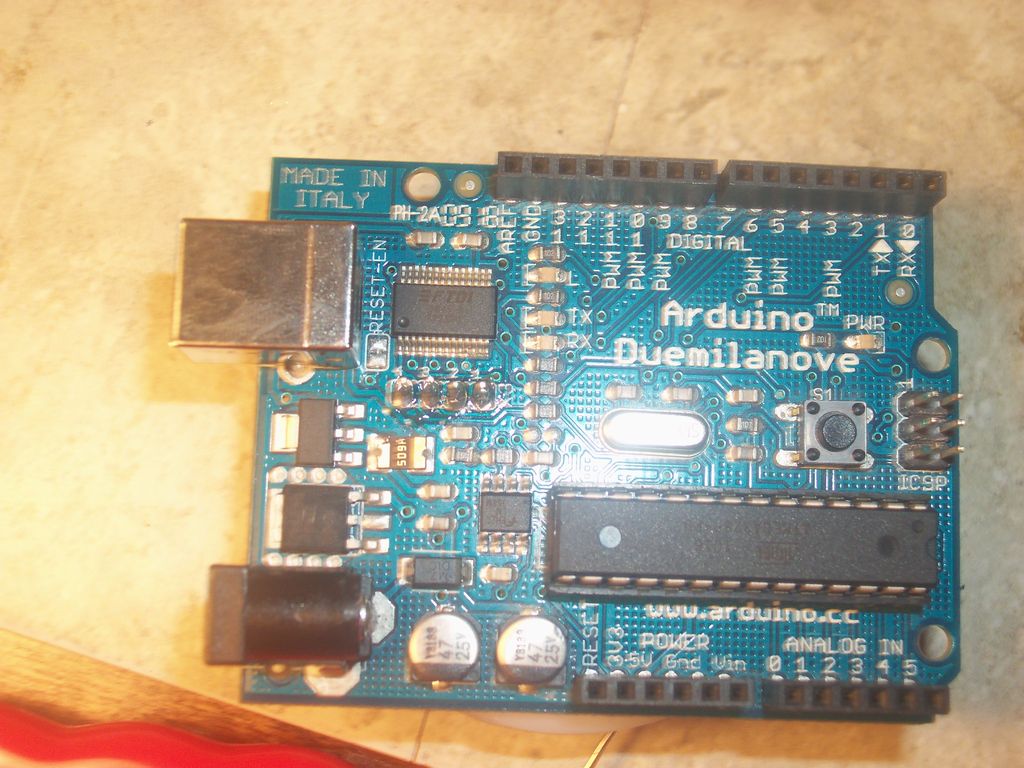
OH NO!!! You’ve screwed up and now the Arduino bootloader on your ‘duino is gone! What are you going to do? Go spend money for a programmer??? Well don’t! I’ve got a solution that only requires your ‘duino and some wires! So its not the end of the world, it is just a minor glitch in the space-time continuum!!! In just under an hour you can have your ‘duino back!***
How?
Well you know those pads near the USB that have the label X3? Well those will become your programmer!!!
Ok, ok. Not everybody messes up, but this will help you if you want to put the bootloader on a new chip, or you actually do mess up. This setup can even program other AVR’s using ICSP.
***The amount of time you will spend is not garunteed to be under an hour, and I will NOT take responsibility if you can’t reprogram your bootloader.
!!!This will not work with the Uno or Mega2560!!!
Step: 1 What You Need
This programmer requires minimal physical components, only wire, an Arduino, (with the FDTI USB to Serial converter built in, so no Uno, Pro, Lilypad, Mega2560, etc.) and a soldering iron and solder.
However, you will need some programs and files to operate the programmer.***
Below are the included program files.
avrdude-GUI
avrdude.conf
serjtag-0.3
The last download wouldn’t work so the link is to the page where you will find it. You will have to scroll down until you find the link labeled serjtag-0.3.zip. The mirror site is the one that works. Save all 3 files in one folder where ever you would like, we will get to those in a minute.
***Currenly available for Windows only.All files are virus FREE.
Step: 2 The Hardware Setup
There are a few methods:
1. You can connect the pins to the pin header on the board, which would go as follows: Pin 1 on the X3 would connect to pin 12 on 2009 and Diecimila or pin 50 on Mega. Pin 2 would connect to pin 13 on 2009 or Diecimila or pin 52 on Mega. Pin 3 would connect to pin 11 on the 2009 and Diecimila or pin 51 on Mega. Pin 4 of the X3 would connect to the RESET pin.
2. You can run jumpers to the ICSP pin header, which would go as follows: Pin 1 would connect to pin 1 on the ICSP header. Make sure that it is pin 1, it should be labeled. Pin 2 would connect to pin 3. Pin 3 would connect to pin 4. And finally, pin 4 would connect to pin 5.
3. Tha last way is to use a 6 or 10 pin (must have a 6 pin connector on it as well for Arduino ICSP) ISP cable. To connect the 6 pin connector to your arduino, you need to find the ICSP pins, then when you plug the connector in, the wires should cover the reset button – on the 2009 and Dieimila only! On the Mega, they should not cover the reset button, but instead cover part of the chip. Connecting the X3 pins is a bit trickier. Below shows the pinouts in picture 5. Pin 1 is in the top right when you look at the pin connectors, and the wires are going to the right!!*** For the 6 pin connector, pin 1 of the X3 goes to pin 1. Pin 2 of the X3 goes to pin 3. Pin 3 of the X3 goes pin 4 of the connector. Pin 4 of the X3 goes to pin 5. For the 10 pin connector, pin 1 of the X3 goes to pin 9. Pin 2 of the X3 goes to pin7. Pin 3 goes to pin 1 and pin 4 goes to pin 5.
***Refer to pictures 6 and 7. Also be careful because the pin diagrams show pin 1 on the left. but it should be on the right. The reason is that the diagram is of the pin headers, not the cable.
Step: 3 The Software Setup
Remember those files you downloaded and saved? Well now your going to set them up.
We are going to start with the folder named serjtag-0.3.zip. First you will want to upzip the folder and save it somewhere. Next, open it up, then open the folder inside named avrdude-serjtag. Next open up the “binary” folder. Inside you should see an avrdude.CONF file, an avrdude.exe file, a COPYING text document and a ftd2xx.dll file. Leave that window open, and open the folder where all of the downloads are stored and copy the avrdude.CONF file from it into the serjtag folder that you were working with. Replace the document and now your good with that.
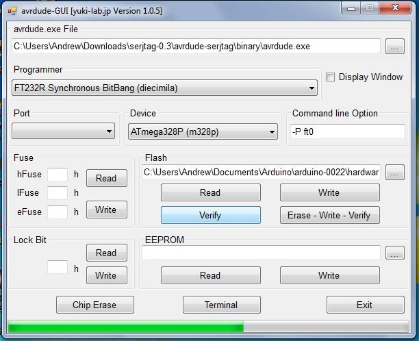
Next, to setup the actual program. Open the folder with the downloads, and open the avrdude-GUI.exe file. This is the actual program.
You will need to find the input field with the title “avrdude.exe File” Click on the browse box next to the input field and find the serjtag folder and go into the avrdude-serjtag folder then binary folder and select the avrdude.exe file.
Next select the programmer: FT232R Synchronous BitBang (diecimila).
The device: Either ATmega168p, ATmega328p or ATmega1280.
NOTE: Leave the port box empty!!!
The Command line operation: -P ft0 -B 4800
Now you’re ready to go!
Step: 4 Running avrdude
On the first test, you are going to read the device’s fuses. In the Fuse category, click read. In a few seconds you should get the fuses. If you get an error message, first make sure that the ‘duino is connected, then if it persists, see the troubleshooting page.
If its a success, then try reading the lockbit. If you can read the lock bit too, then you can set the fuses.
Click the Chip Erase button. Then choose the correct fuse settings from below:
Duemilanove ATmega328
hFuse=DA
lFuse=FF
eFuse=05
Lock Bit=3F
Duemilanove ATmega168/Diecimila:
hFuse=DD
lFuse=FF
eFuse=00
Lock Bit=3F
Mega:
hFuse=DA
lFuse=FF
eFuse=F5
Lock Bit=3F
For more detail: Programming Arduino Bootloader without Programmer using ATmega168 microcontroller


