Summary of Salvaging Liquid Crystal Displays (LCDs)
This Instructable explains how to salvage, identify, and test various Liquid Crystal Displays (COG, TN, STN, FSTN) from devices like printers. It covers disassembly tips, common pinouts, removing ribbon sockets, and using an Arduino with LiquidCrystal library to test 16×2 and 16×1 modules, including modified code for 16×1 displays. Datasheet resources and practical soldering/removal techniques are provided to increase successful salvage and reuse.
Parts used in the Salvaging Liquid Crystal Displays (LCDs):
- Assorted Phillips Screwdrivers
- Assorted Torx Screwdrivers
- Assorted Pliers
- Side Cutters
- Spring Loaded Tweezers
- Large Soldering Iron
- Small Soldering Iron
- Utility Knife
- Dremel Set
- Arduino UNO Kit
- Wires
- Solder
- Goop Glue
- Printer/scanner (HP psc 750xi used for disassembly)
- Ribbon socket (salvaged from control board)
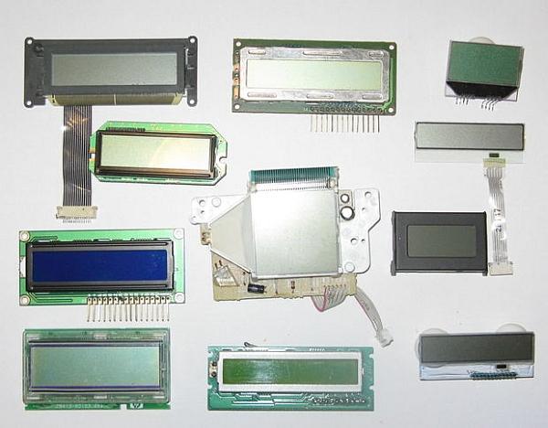
Almost all electronics have some sort of human interface, from blinking lights and beeping speakers to seven segment alphanumeric and Liquid Crystal Displays. This Instructable is about salvaging and testing Liquid Crystal Displays, and a couple tricks I know to make salvaging them more successful.
I salvage; components can get expensive, LCDs can run $10.00 and up even SCRs and mosfets can cost over $100.00 so I salvage everything of reusable value as well as recyclable. Scrap metals like copper, gold, silver, and aluminum can bring you money as well.
Liquid Crystal Displays can be found on CD players, Phones, and printers just to mention a few. In this Instructable I will be dissembling an HP combination printer, scanner, fax machine.
Step 1: Tools & Supplies
Assorted Phillips Screwdrivers
Assorted Torx Screwdrivers
Assorted Pliers
Side Cutters
Spring Loaded Tweezers
Large Soldering Iron
Small Soldering Iron
Utility Knife
Dremel Set
Arduino UNO Kit
Wires
Solder
Goop Glue
Step 2: Disassembling a HP psc 750xi
Printers & scanners are simple to dissemble, just remove the screws and take out the parts most of the screws are under the lid, on the back, and on the bottom of the printer & scanner.
Even when the screws are removed the plastic housing panels are clipped together with tabs holding them in place. Work your way around the individual panels to find the tabs and unclip them. Plastic is recyclable and some plastic recyclers pay for the plastic so don’t just throw the plastic in the garbage.
The control module of the printer scanner contains the control buttons and the Liquid Crystal Display. It dissembles by removing the five screws on the back.
I sort the parts into two groups Electronics to be stripped for parts and gold, and mechanics like guides, gears, and stepper motors.
Remember metal is recyclable and almost all recyclers pay for scrap metal so if you don’t keep it sell it.
Although the LCD module looks different than the other TN STN FSTN LCD modules in this Instructable it is connected the same way when testing.
Step 3: Chip on Glass Liquid Crystal Displays (COG LCD)
As well as the attached datasheet here is some pin outs for COG displays, many of the data sheets have the Display in the part number such as, S161COG, 16×1 COG display, S162COG, 16×2 COG display, and 64128L 128×64 graphic LCD display.
The contrast circuit for COG LCDs is the same as the contrast circuit as TN, STN, FSTN module.
Pins Right to Left
8 Pin 16×2 Character COG LCD
PIN SYMBOL FUNCTION
1 VOUT DC/DC Converter Out
2 VC Capacitor Positive (-) side
3 VCC Capacitor Negative (+) side
4 VDD Power Supply for Logic
5 VSS 0 Volts Ground
6 SDA Serial Data Input
7 SCL Serial Clock
8 RST Reset Signal L = Active
8 Pin 16×2 Character COG LCD
1 RST Reset Signal L = Active
2 SCL Serial Clock
3 SDA Serial Data Input
4 VSS 0 Volts Ground
5 VDD Power Supply for Logic
6 VOUT DC/DC Converter Out
7 VC Capacitor Positive (-) side
8 VCC Capacitor Negative (+) side
Displaytech 14 Pin 16X2 Character COG LCD
Pins Left to Right
PIN SYMBOL FUNCTION
1 VSS 0 Volts Ground
2 VO Contrast Adjustment
3 VDD +3 or +5 Volts Power Supply
4 RS Register Select Signal L = Instruction H = Data
5 R/W Read/Write Select Signal L = Write H = Read
6 E Enable Signal
7 DB0 Data Bus
8 DB1 Data Bus
9 DB2 Data Bus
10 DB3 Data Bus
11 DB4 Data Bus
12 DB5 Data Bus
13 DB6 Data Bus
14 DB7 Data Bus
 16×2 COG LCD.pdf342 KB
Step 4: Salvaging COG LCDs
I like to get my datasheets from these two web sites:
http://www.maxim4u.com/
http://www.alldatasheet.com/
You can just pull the LCD however finding just the right ribbon socket can be hard, so the only part I need from the circuit board to use this COG LCD else where is the ribbon socket. (Inside the yellow rectangle) I do this by placing my large soldering iron on the back of the circuit board and when the solder melts I lift off the socket.
MM74HC374WM.pdf88 KBStep 5: TN STN and FSTN Liquid Crystal Display Modules (LCD Modules)
10, 12, 14, and 16 Pin
8×1, 8×2, 10×1, 10×4, 16X1, 16X2, 16×4, 20×2, 20×4, 24×2, 40×2 LCD
PIN SYMBOL FUNCTION
1 VSS 0 Volts Ground
2 VDD +3 or +5 Volts Power Supply
3 VO Contrast Adjustment
4 RS Register Select Signal L = Instruction H = Data
5 R/W Read/Write Select Signal L = Write H = Read
6 E Enable Signal
7 DB0 Data Bus
8 DB1 Data Bus
9 DB2 Data Bus
10 DB3 Data Bus
11 DB4 Data Bus
12 DB5 Data Bus
13 DB6 Data Bus
14 DB7 Data Bus
15 A/Vee Backlight Anode +4.2 Volts
16 K Backlight Cathode Power Ground
Step 6: Testing 16X2 TN, STN, FSTN 16 Pin LCD Modules
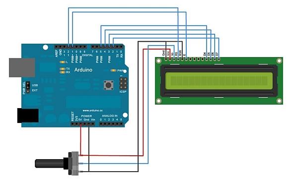
I use Arduino to test the modules and check the functions to make sure they work properly, this is the hookup and code for the 16×2, 16 pin LCD.
You can copy and paste the code below into sketch:
/*
LiquidCrystal Library – Hello World
Demonstrates the use a 16×2 LCD display. The LiquidCrystal library works with all LCD displays that are compatible with the
Hitachi HD44780 driver. There are many of them out there, and you can usually tell them by the 16-pin interface.
This sketch prints “Hello World!” to the LCD
and shows the time.
The circuit:
* LCD RS pin to digital pin 12
* LCD Enable pin to digital pin 11
* LCD D4 pin to digital pin 5
* LCD D5 pin to digital pin 4
* LCD D6 pin to digital pin 3
* LCD D7 pin to digital pin 2
* LCD R/W pin to ground
* 10K resistor:
* ends to +5V and ground
* wiper to LCD VO pin (pin 3)
Library originally added 18 Apr 2008
by David A. Mellis
library modified 5 Jul 2009
by Limor Fried (http://www.ladyada.net)
example added 9 Jul 2009
by Tom Igoe
modified 22 Nov 2010
by Tom Igoe
This example code is in the public domain.
http://www.arduino.cc/en/Tutorial/LiquidCrystal
*/
// include the library code:
#include <LiquidCrystal.h>
// initialize the library with the numbers of the interface pins
LiquidCrystal lcd(12, 11, 5, 4, 3, 2);
void setup() {
// set up the LCD’s number of columns and rows:
lcd.begin(16, 2);
// Print a message to the LCD.
lcd.print(“hello, world!”);
}
void loop() {
// set the cursor to column 0, line 1
// (note: line 1 is the second row, since counting begins with 0):
lcd.setCursor(0, 1);
// print the number of seconds since reset:
lcd.print(millis()/1000);
}
Step 7: Code for the 16×1 LCD
Using Arduino to test the 16×1 modules and check the functions; I found that the 16×2 code needed to be modified because the IC looked at the 16×1 LCD as two lines and all you see is the first eight segments of the display.
This is the code for the 16×1 14 and 16 pin LCD.
/*
LiquidCrystal Library – Hello World
Demonstrates the use a 16×1 LCD display; the LiquidCrystal library works with all LCD displays that are compatible with the Hitachi HD44780 driver. There are many of them out there, and you can usually tell them by the 16-pin interface however these are 16×1 LCD, 14 pin interface.
This sketch prints “Hello World!” to the 16×1 LCD.
*/
// include the library code:
#include <LiquidCrystal.h>
// initialize the library with the numbers of the interface pins
LiquidCrystal lcd(12, 11, 5, 4, 3, 2);
void setup() {
// set up the LCD’s number of columns and rows:
lcd.begin(8, 2); //is 16×1, adressed as 8×2
lcd.setCursor(0,1); //init right hand side
lcd.home(); //back to start
lcd.clear();
// Print a message to the LCD.
lcd.print(“hello wo”); //print left side
lcd.setCursor(0,1); //go to right
lcd.print(“rld!”); //print right side
//blinking cursor
lcd.cursor();
lcd.blink();
}
void loop() {
}
For more detail: Salvaging Liquid Crystal Displays (LCDs)
- Where can I commonly find LCDs to salvage?
LCDs can be found on CD players, phones, and printers such as an HP combination printer, scanner, fax machine. - What tools are needed to disassemble a printer to get the LCD?
Assorted Phillips and Torx screwdrivers, pliers, side cutters, tweezers, soldering irons, utility knife, and Dremel are used. - How do you remove a ribbon socket from the circuit board?
Place a large soldering iron on the back of the circuit board until the solder melts, then lift off the socket. - What are Chip on Glass COG LCDs?
COG LCDs have the driver IC on the glass near the input pins or ribbon connector and come in serial or parallel data input versions. - What common pinouts do TN, STN, and FSTN LCD modules use?
Common pinouts include VSS, VDD, VO (contrast), RS, R/W, E, and DB0–DB7; pins for backlight A/Vee and K appear on pins 15 and 16 for some modules. - How can I test a 16×2 16-pin LCD module?
Use an Arduino with the LiquidCrystal library wired: RS to pin 12, E to 11, D4–D7 to pins 5,4,3,2, R/W to ground, and a 10K potentiometer to VO. - Do 16×1 LCDs require different code than 16×2 when testing?
Yes; 16×1 modules are often addressed as 8×2, so lcd.begin(8,2) and cursor positioning are used to display both sides. - Where can I find datasheets for LCD driver ICs?
The Instructable recommends maxim4u and alldatasheet websites for datasheets.