Summary of Stone LCD is used together with STM32
This article details integrating an STM32F103C8T6 microcontroller with a Stone LCD display using STM32CubeMX, focusing on RS232 communication via MAX232 and implementing a slider for PWM control. The project replaces previous Arduino methods with STM32 specific configurations, utilizing UART interrupts for screen data and timers for delays and ADC sampling.
Parts used in the Stone LCD STM32 Project:
- STM32F103C8T6 Processor
- Stone LCD Screen
- MAX232 IC
- Transistors (for previous circuit reference)
- Four LEDs
- Potentiometer
- Fuse Capacitor (1uF to 100nF)
- UART Interface
- Timer 3 for PWM generation
- ADC Module
We will be changing how we use the Stone LCD with the STM32 series cards that we used to use with the Arduino. However, we will be using the STM32CubeMx and I have tried to provide the editor with detailed space in writing for use with the Arduino, so I will not be detailing this in the same way. You can access the previous article. I have only added the previous design slider to this application. I will show you how to add the slider to the editor and how to complete the setup. Secondly, as I mentioned before, I have been able to use the RS232 screen to communicate with other devices. In my previous article I made a transistor solution because I didn’t have a machine to convert RS232 from UART to MAX232, now I’m going to show you that you need to create circuits with MAX232.
Let’s start with the circle, the fuse line of the circle is like the bottom. If you are going to use this box, you should be careful. You can choose a value between 1uF and 100nF. If you don’t understand exactly what this circuit means, you can write down “MAX232 TTL circuit” on the internet to see a different circuit diagram. I used these pins because I needed one and you can see them on the web as different pins.
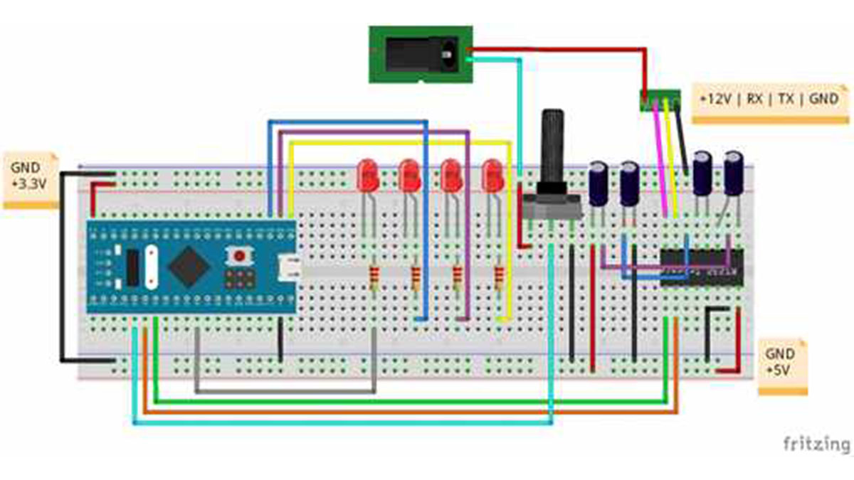
In addition to the MAX232 integration, there are four LEDs and a potentiometer. These guys are turned on the screen to show the tool in use, just like everyone else. The blinking of the three LED buttons will change the display values on the potential screen. 4 The left LED is connected to the PWM tube to change the brightness of the slider we added.
Open it after creating the screen design. I used the same design as the screen design. There are only 4. I created a page and added the sliders. I’ll just show you how the slider works. I got a slider design from the freepik on the page and added the slider on the background with the help of Photoshop. The slider must have a background as well. You need to convert the bitmap to a separate indicator and add it as an icon. At this point, if you want the icon to be transparent, as explained in the previous paragraph, you have to darken the background color of the bitmap. Image of the page. You will need to use two tools to add the slider. These tools are marked in red on the image below. One tool is used to identify where the slider icon will move and the other tool identifies the location where the touch activity will be captured. These two tools need to identify the same memory address because they have the same purpose.

I have added an icon to use the slider as it appears in the blue part of the image above. This icon will be used for the “slider zoom” tool. It is a tool to determine the position of the scroll area, called “drag and drop adjustment”. The settings for these tools can be found in the image below. I have added a ‘data variable’ tool to see the value of the slider on the page. As I said before, vehicles for the same purpose must have the same address, so when configuring the vehicle properties, I have to put all three vehicles in the same place, which I have defined as 4001, don’t forget that the address is in hexadecimal format.

When the slider’s setup is complete, see how the slider sends data as it changes the slider value. In fact, the slider’s data format is no different than the button. We will use the same data separation method that we used for the button before. Only because we are using a slider instead of a button, the data address will be different. By viewing this address, you must do so with the question you wish to answer. When we use sliders on the screen, the format of the data you want to perform is like the one below.
[Header 1, Header 2, Packet Length, Data Type, Address 1, Address 2, Data Length, Data 1, Data 2]
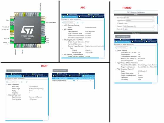
If you want to pay attention to this format, it’s the same as the other button I gave you. Here, we have to create a software to decide if the data from address 1 and address 2 is a slider. For the STM32′at UART, the UART interface to the screen should also be disconnected. This allows the microgeneration to leave work and go to the cut function, especially fast. The probability of data loss in the data stream is low, now let’s look at the settings to be made in CubeMX, I will be using the STM32F103C8T6 as the processor, you can customize CubeMX to the processor you have.The diagram below shows the settings I have made in CubeMX for the STM32F103 processor. You’ll have to pay attention to some of the parts here. The first UART ball is the 115200 and global interrupts, and the other is the prescaler and counter period settings for Timer 3. This is how I set the PWM frequency. I entered these settings because I want the PWM frequency to be 1Khz. the counter period is 999 which means our maximum PWM value can be 999. in the Arduino, to the user, this could be a signal that this value is not 255. it all depends on the timer settings. This is similar to the Arduino. The following image does not appear to process time. The worksheet is set to the highest value of 72Mz that has been selected. Don’t forget that this frequency will be appreciated when the timer frequency is set.
Since we’ve completed these settings in CubeMx, it’s now time for software development. First, let’s see how to activate the UART via interrupts, because this part has an important detail. You can use the function given below to start UART in interrupt mode. but you have to enter the size as parameter as shown in the function. So you have to specify the number of bytes coming from UART and this cut should be active. In this application, the length parameter of the buttons and sliders we use on the screen does not change the length of the data, but if the length of the data coming from the UART changes, we cannot use the UART in interrupt mode. no. I’ll just suggest two possible solutions for those who are stuck inside. After activating the first HAL library, using UART’s IRQHandler is a bit more difficult, but more professional. The second way to use UART in DMA is to browse through all the buffers when you select a DMA buffer that is larger than the packet on UART. First, it’s slower, but easier to solve.
HAL_UART_Receive_IT(&huart2, readData, BUFF_SIZE); // start receiving uart using interrupt
HAL_TIM_PWM_Start(&htim3, TIM_CHANNEL_1); // start pwm
Having selected a UART with interrupt, let’s see if we can perform a guaranteed cut. The goal of the interrupt is to ensure that, as we noted earlier, another job is completed ahead of schedule at the end of the job, but using the interrupt function. We need to complete this process as quickly as possible and create a software that attempts to return to the main loop. using the UART function again in a UART cut can cause some problems. For these reasons it has to be as little work as possible and I only use a flag that the data is coming and ready to go.
// if data received from uart set uart flag variable
void HAL_UART_RxCpltCallback(UART_HandleTypeDef *huart)
{
uartFlag = 1;
}
Looking at this flag, I can perform my actions in the main cycle. What I do in the main cycle is as follows. One thing we need to be careful of again. In order to do this, we need to show that there is no structure that can be used to delay the parent loop. As long as we use UART cut, the next data segmentation will be delayed and the wait time will cause packet loss, so what happens if we need to delay. In this case, we need to use a timer. In this software, I used the timer to help create a delay, but I’m not going to go into detail about how it works. In the future, I will explain in detail how to create mm functions using STM32.
if(uartFlag) // if uart packet received
{
if(readData[0] != 0xA5 && readData[1] != 0x5A) continue; // check packet first and second bytes
uint16_t mAdr = (readData[4] << 8) | (readData[5]); // get adress from received packet
uint16_t mData = (readData[7] << 8) | (readData[8]); // get value from recived packet
switch (mAdr) // choose adress
{
case 0x16A1: //button1 adress
HAL_GPIO_TogglePin(LED1_GPIO_Port, LED1_Pin);
break;
case 0x16A2: //button2 adress
HAL_GPIO_TogglePin(LED2_GPIO_Port, LED2_Pin);
break;
case 0x1992: //switch adress
HAL_GPIO_WritePin(LED3_GPIO_Port, LED3_Pin, (mAdr == 1 ? GPIO_PIN_SET : GPIO_PIN_RESET));
if(mData) //send string value according to switch status
{
HAL_UART_Transmit(&huart2, arrOn, sizeof(arrOn), 1000);
}else{
HAL_UART_Transmit(&huart2, arrOff, sizeof(arrOff), 1000);
}
break;
case 0x4001: // get slider value and write pwm
__HAL_TIM_SET_COMPARE(&htim3, TIM_CHANNEL_1, mData * 10);
break;
}
uartFlag = 0; // clear uart flag variable
}
After I multiplied the data index, as you can see in the software blog above, I used a switch – a case structure from the address – and in fact, those parts are not too different from the previous one. I only created a case for the data from address 0x4001. Since we set the slider to a maximum value of 100, the UART sends at least 100 data, so I sent it as PWM using 10 times the value we read from one side to the other. As I mentioned above, we made sure the PWM was the maximum 999.
I’m performing the ADC read in polling mode. This is the way I don’t like to hear too fast or too many samples. Since the ADC is 12-bit, the read will be somewhere between 0 and 4096. I divide 8′e by the value displayed on the screen to reduce that value. Thus, the read ADC value is somewhere between 0 and 512.
HAL_ADC_Start(&hadc1); // start adc conversion
HAL_ADC_PollForConversion(&hadc1, 1000); // wait for conversion end
adcVal = HAL_ADC_GetValue(&hadc1); // get adc value
adcVal = adcVal / 8; // scale adc value
HAL_ADC_Stop(&hadc1); // stop adc conversion
Finally, update the display values. The process of transferring data to the operator with a universal asynchronous transceiver (UART) is incorrect. Since the data he reads from the UART is always available, we solved this problem using Arduino milliseconds, and we can use a similar process here. Or we can solve the problem by setting a timer. So we could send one screen data every 100 milliseconds. I’ve chosen the first route.
if(mMilis – lastTime1 > 100) // make in every 100ms
{
HAL_GPIO_TogglePin(LED4_GPIO_Port, LED4_Pin);
// send high and low bytes of adc value in different bytes
uint8_t sendValL = adcVal & 0xFF;
uint8_t sendValM = (adcVal & 0xFF00) >> 8;
arr[6] = sendValM;
arr[7] = sendValL;
HAL_UART_Transmit(&huart2, arr, sizeof(arr), 1000); // send adc value with UART to show in gauge
lastTime1 = mMilis;
}
We have completed all the settings and are ready to use the screen. You can connect to the entire software we created.http://www.slw-ele.com
- How do I convert RS232 signals for the STM32?
You must create a circuit using a MAX232 chip to convert RS232 from UART. - What capacitor values are recommended for the MAX232 fuse line?
You can choose a value between 1uF and 100nF for the fuse line capacitors. - How should the slider icon and touch activity be configured in the editor?
Both tools must identify the same memory address to function correctly together. - What is the data format structure for the slider?
The format follows [Header 1, Header 2, Packet Length, Data Type, Address 1, Address 2, Data Length, Data 1, Data 2]. - Why is it necessary to disconnect the UART interface during processing?
Disconnecting allows the microcontroller to perform other tasks quickly and reduces the probability of data loss. - What PWM frequency was set for Timer 3 in CubeMX?
The PWM frequency was set to 1Khz with a counter period of 999. - How does the software handle UART data reception efficiently?
The code uses a flag variable set by the interrupt callback to process data in the main loop without blocking. - How is the ADC value scaled for the display?
The 12-bit ADC reading is divided by 8 to reduce the range from 0-4096 to 0-512. - How often is the display updated with new ADC data?
The system updates the display values every 100 milliseconds.