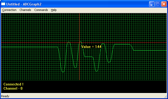
ADC (Analog to digital converter) is a commonly used peripheral. We use it everyday to interface with several analog sensors. Many times a nice visualization of ADC data is required during learning about new sensors. For example you just bought a analog sound sensor, and try to do some fast experiments that how it performs. In this situation this valuable tool will come to your help. The tool I called is ADCGraph2, it is being with me from a long time but today I thought of sharing it publicly. I wrote this tool somewhere 4 years back to experiment with sensors like LDRs, Temperature Sensor, Audio input etc. The public version is improved form of my in-house tool.
The ADCGraph2 is a simple Windows Based Tool that connect with an ATmega32 microcontroller (running a special firmware) to receive ADC data from any selected channels (0-7) and show a nice graph on PC screen. You can connect the output of any analog sensor to any ADC input pin and view the sensors output on PC screen in form of a nice graph. The connection is over USART Port so you need a USB to UART Bridge.
Using the software is simple. First make sure that xBoard v2.0 is flashed with the ADCGraph firmware (details on building the hardware is given below) and connected to USB to UART Bridge which is connected to your PC (Make sure drivers are installed, link to driver are given on this page).
Click “Connect” from the “Connection Menu”and select the COM Port where USB to UART Bridge is present. To find out which COM Port number is assigned to the USB to UART Bridge see this article(scroll to the end).
Select Baud Rate as 19200. And click OK.
If everything was OK then a success message will be shown.
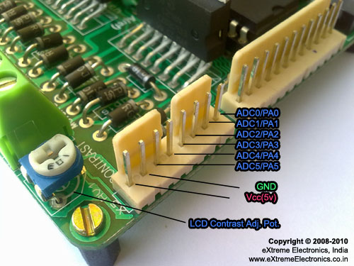
Now you can start sampling the ADC by Selecting “Start Sampling” from the “Command” menu. On start-up channel 0 is selected, so it will show the analog value that is present on ADC0 pin. The pin out of ADC port on xBoard v2.0 is given below.
You can change the input channel anytime by selecting it from “Channels” menu.
For testing purpose you may apply signals to the ADCx pins using a variable resistor (POT) as a potential divider as described below.
Connect the LEFT PIN to GND, RIGHT PIN to 5v and the CENTER PIN to INPUT of ADC with a 10K resistor in series. Now you can rotate the POT to vary the Input to ADC from 0v to 5v.
For more detail: Visualize ADC data on PC Screen using USART AVR Project using microcontroller


