Summary of Wireless Gesture Controlled Robot Using Micro-controller ATmega328
This article details a wireless gesture-controlled robot project where hand tilts detected by an ADXL335 accelerometer control a robot via an ATmega328 microcontroller and 433MHz RF modules. The system uses HT12E/HT12D for data encoding/decoding and an L293D driver for motor control, enabling remote operation suitable for hazardous environments like nuclear plants.
Parts used in the Wireless Gesture Controlled Robot:
- IC1 - 7805, 5V regulator
- IC2 - ATmega328 microcontroller
- IC3 - LM1117-33, 3.3 voltage regulator
- IC4 - HT12E, 2 12 series encoder
- IC5 - HT12D, 2 12 series decoder
- IC6 - L293D, dual H-bridge motor driver
- LED1 & 4 - 5mm LED
- R1 - 1-mega-ohm resistor
- R2 - 10-kilo-ohm resistor
- R3 - 750-kilo-ohm resistor
- R4-R7 - 220-ohm resistors
- R8 - 47-kilo-ohm resistor
- C1, C2 - 22pF ceramic disk capacitors
- C3 - 0.1μF ceramic disk capacitor
- C4 - 0.33μF ceramic disk capacitor
- C5 - 10μF, 16V electrolytic capacitor
- CON1, CON3 - 2-pin connector
- CON2 - 6-pin connector
- X TAL 1 - 16MHz crystal
- TX1 - 433MHz transmitter module
- RX1 - 433MHz receiver module
- M1, M2 - DC-geared motor, 100rpm
- S1, S2 - On/off switch
- Batt.1 - 9V PP3 battery
- Batt.2 - 4.5V, 1.5Ah lead-acid battery
- ANT.1, ANT.2 - 17cm long single-strand wire antenna
- ADXL335 3-axis accelerometer
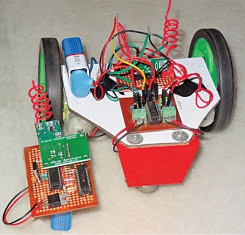
In this wireless gesture controlled robot project I am going to control a robot using hand gestures. This is an easy, user-friendly way to interact with robotic systems and robots. An accelerometer is used to detect the tilting position of your hand, and a microcontroller gets different analogue values and generates command signals to control the robot. This concept can be implemented in a robotic arm used for welding or handling hazardous materials, such as in nuclear plants.
Step 1: Circuit Components
- Semiconductors
- IC1 – 7805, 5V regulator
- IC2 – ATmega328 microcontroller
- IC3 – LM1117-33, 3.3 voltage regulator
- IC4 – HT12E, 2 12 series encoder
- IC5 – HT12D, 2 12 series decoder
- IC6 – L293D, dual H-bridge motor driver
- LED1 & 4 – 5mm LED
- Resistors (all 1/4-watt, ±5% carbon):
- R1 – 1-mega-ohm
- R2 – 10-kilo-ohm
- R3 – 750-kilo-ohm
- R4-R7 – 220-ohm
- R8 – 47-kilo-ohm
- Capacitors:
- C1, C2 – 22pF ceramic disk
- C3 – 0.1μF ceramic disk
- C4 – 0.33μF ceramic disk
- C5 – 10μF, 16V electrolytic
- Miscellaneous:
- CON1, CON3 – 2-pin connector
- CON2 – 6-pin connector
- X TAL 1 – 16MHz crystal
- TX1 – 433MHz transmitter module
- RX1 – 433MHz receiver module
- M1, M2 – DC-geared motor, 100rpm
- S1, S2 – On/off switch
- Batt.1 – 9V PP3 battery
- Batt.2 – 4.5V, 1.5Ah lead-acid battery
- ANT.1, ANT.2 – 17cm long single-strand wire antenna
- – ADXL335 3-axis accelerometer
Step 2: What Are Those?
ATmega328
ATmega328 is a single-chip microcontroller from Atmel and belongs to the mega AVR series. The Atmel 8-bit AVR RISC based microcontroller combines 32kB ISP flash memory with read-while-write capabilities, 1kB EEPROM, 2kB SRAM, 23 general-purpose I/O lines, 32 general-purpose working registers, three flexible timers/counters with compare modes, internal and external interrupts, serial programmable USART, a byte-oriented 2-wire serial interface, SPI serial port, 10-bit A/D converter, programmable watch-dog timer with an internal oscillator and five software-selectable power-saving modes.The device operates between 1.8 and 5.5 volts. It achieves through puts approaching one MIPS per MHz. An alternative to ATmega328 is ATmega328p.
ADXL335
This is a complete three-axis acceleration measurement system. ADXL335 has a minimum measurement range of ±3g. It contains a poly-silicon-surface micro-machined sensor and signal-conditioning circuitry to implement open-loop acceleration measurement architecture. Output signals are analogue voltages that are proportional to acceleration. The accelerometer can measure the static acceleration of gravity in tilt-sensing applications as well as dynamic acceleration resulting from motion, shock or vibration.
The sensor is a poly-silicon-surface micro-machined structure built on top of a silicon wafer. Poly-silicon springs suspend the structure over the surface of the wafer and provide resistance against acceleration forces. Deflection of the structure is measured using a differential capacitor that consists of independent fixed plates and plates attached to the moving mass.
Fixed plates are driven by 180° out-of-phase square waves. Acceleration deflects the moving mass and unbalances the differential capacitor, resulting in a sensor output whose amplitude is proportional to acceleration. Phase-sensitive demodulation techniques are then used to determine the magnitude and direction of the acceleration.
L293D
This is a 16-pin DIP package motor driver IC (IC6) having four input pins and four output pins. All four input pins are connected to output pins of the decoder IC (IC5) and the four output pins are connected to DC motors of the robot. Enable pins are used to enable input/output pins on both sides of IC6.
Encoder (HT12E) and decoder (HT12D) ICs
The 212 encoders are a series of CMOS LSIs for remote-control system applications. These are capable of encoding information that consists of N address bits and 12 N data bits. Each address/data input can be set to one of two logic states. Programmed addresses/data are transmitted together with header bits via an RF or infra-red transmission medium upon receipt of a trigger signal. The capability to select a TE trigger on HT12E or a data (DIN) trigger on HT12D decoder further enhances the application flexibility of 212 series of encoders. The HT12D also provides a 38kHz carrier for infra-red systems.
Transmitter
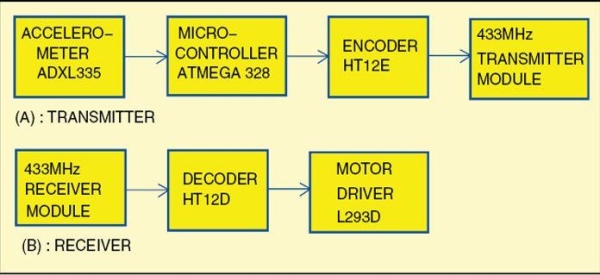
The transmitter consists of ATmega328 microcontroller (IC2), ADXL335 accelerometer, HT12E encoder (IC4) and 433MHz RF transmitter module (TX1). In this circuit, two analogue outputs from ADXL335 pins (x, y) are connected with input pins (23, 24) of the microcontroller. Analogue signals are converted to digital signals through the microcontroller. Digital outputs from pins 16, 17, 18 and 19 of the microcontroller are directly sent to pins 13, 12, 11 and 10 of encoder IC4. This data is encoded and transmitted via RF module TX1.
Receiver
The receiver part consists of 433MHz RF receiver module (RX1), HT12D decoder (IC5) and L293D motor driver (IC6) to run the motors. Here, receiver module RX1 receives the transmitted signal, which is decoded by decoder IC to get the same digital outputs. Four outputs of IC6 drive two motors. The robot moves as per tilt direction of the accelerometer in the transmitter.
Step 3: Block Diagram
Step 4: Transmitter and Receiver Circuit
Step 5: PCB Layout of Receiver and Transmitter Circuit
The first two images are the layout of receiver circuit and the other two images are the layout of transmitter circuit.
Step 6: Software Program
The software program is written in Arduino programming language. I programmed a fresh ATmega328 microcontroller with the help of Arduino IDE 1.0.5 and an Arduino Uno board.
First,you have to load bootloader code into the microcontroller. For that, I used Arduino Uno for in-system programming (ISP) given in the IDE, by selecting File → Examples → Arduino ISP. Once the bootloader is uploaded into the microcontroller, gesture.ino code of this project can be uploaded.
Step 7: Source Code
const int ap1 = A0;
const int ap2 = A1;
int sv1 = 0;
int ov1 = 0;
int sv2 = 0;
int ov2= 0;
void setup()
{ // initialize serial communications at 9600 bps:
Serial.begin(9600);
pinMode(13,OUTPUT);
pinMode(12,OUTPUT);
pinMode(11,OUTPUT);
pinMode(10,OUTPUT);
}
void loop()
{ analogReference(EXTERNAL); //connect 3.3v to AREF
// read the analog in value:
sv1 = analogRead(ap1);
ov1 = map(sv1, 0, 1023, 0, 255);
delay(2);
sv2 = analogRead(ap2);
ov2 = map(sv2, 0, 1023, 0, 255);
delay(2);
Serial.print(“Xsensor1 = ” );
Serial.print(sv1);
Serial.print(“\t output1 = “);
Serial.println(ov1);
Serial.print(“Ysensor2 = ” );
Serial.print(sv2);
Serial.print(“\t output2 = “);
Serial.println(ov2);
if(analogRead(ap1)<514 &&analogRead (ap2)<463) // for backward movement
{
digitalWrite(13,HIGH);
digitalWrite(12,LOW);
digitalWrite(11,HIGH);
digitalWrite(10,LOW);
}
else
{
if(analogRead(ap1)<486 &&analogRead (ap2)>508) // for left turn
{
digitalWrite(13,LOW);
digitalWrite(12,HIGH);
digitalWrite(11,HIGH);
digitalWrite(10,LOW);
}
else
{
if(analogRead(ap1)>512 &&analogRead (ap2)>560) // for forward
{
digitalWrite(13,LOW);
digitalWrite(12,HIGH);
digitalWrite(11,LOW);
digitalWrite(10,HIGH);
}
else
{
if(analogRead(ap1)>550 &&analogRead (ap2)>512)//for right turn
{
digitalWrite(13,HIGH);
digitalWrite(12,LOW);
digitalWrite(11,LOW);
digitalWrite(10,HIGH);
}
else
{
digitalWrite(13,HIGH);
digitalWrite(12,HIGH);
digitalWrite(11,HIGH);
digitalWrite(10,HIGH);
Step 8: Testing
Mount all components on the PCBs shown here to minimise assembly errors. Fix the receiver PCB and 4.5V battery on the chassis of the robot. Fix two motors, along with wheels, at the rear side of the robot and a castor wheel on the front. After uploading the main code into the microcontroller, remove it from the Arduino Uno board and insert it into the populated transmitter PCB.
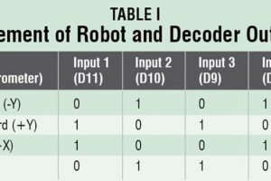
Now, switch-on the power supplies in the transmitter as well as receiver circuits. Attach the transmitter circuit to your hand(or to a gloves) and move your hand forwards, backwards and sideways. Directions of the robot movement are given in Table I. The robot will stop if you keep your palm horizontal, parallel to the Earth’s surface.
For troubleshooting, first verify that voltages at various test points are as per Table II.
Source: Wireless Gesture Controlled Robot Using Micro-controller ATmega328
- How does the robot detect hand movements?
An accelerometer detects the tilting position of your hand, and a microcontroller generates command signals based on different analogue values. - Can this concept be implemented for hazardous materials handling?
Yes, this concept can be implemented in robotic arms used for welding or handling hazardous materials such as in nuclear plants. - What components make up the transmitter circuit?
The transmitter consists of the ATmega328 microcontroller, ADXL335 accelerometer, HT12E encoder, and 433MHz RF transmitter module. - Does the robot stop when the palm is horizontal?
Yes, the robot will stop if you keep your palm horizontal and parallel to the Earth's surface. - What programming language is used for the software program?
The software program is written in Arduino programming language using Arduino IDE 1.0.5. - How are the motors driven in the receiver circuit?
Four outputs of the L293D motor driver IC drive two motors to move the robot as per the tilt direction of the accelerometer. - What happens if voltages at test points are incorrect during troubleshooting?
You must first verify that voltages at various test points match the values listed in Table II before proceeding. - Which microcontroller is used as an alternative to ATmega328?
An alternative to ATmega328 is the ATmega328p.