
Summary of 0 TO 5V OUTPUT ANALOG HALL SENSOR FOR FOOT CONTROLLER
This project utilizes a DRV5053 Hall Effect sensor and an LMV612 Op-Amp circuit to create a non-contact analog position or angular sensing system for foot controllers. It features adjustable offset and gain via trimmer potentiometers, providing a linear 0-5V output range suitable for industrial controls. The design ensures high stability, low power consumption, and adaptability to various magnet types while mechanically balancing the actuator at a mid-point for precise voltage control.
Parts used in Analog Hall Sensor Foot Controller:
- DRV5053 Hall Effect Sensor
- LMV612 Operational Amplifier
- Trimmer Potentiometer PR2 (Offset Adjustment)
- Trimmer Potentiometer PR1 (Gain Adjustment)
- Resistor R3 and Capacitor C4 (RC Filter)
- Resistor R1 and Resistor R8 (Adjustable Parameters)
- Dual-spring Actuator System
- Magnet
This project includes an analog Hall Effect sensor and an Op-Amp circuit which can be used as position or angular sensing with the benefits of no contact and wearing, high stability and wide sensing range. Two configurations of the magnet and Hall sensors are analyzed. Trimmer Potentiometer PR2 provided to adjust the offset and PR1 helps to set the system gain. The Op-Amp circuit helps to achieve the desired output bias and range. The sensor provides an approximately linear response, adapt wide magnet types and field range. DRV5053 Sensor is the heart of the project. The DRV5053 device is a chopper-stabilized Hall IC that offers a magnetic sensing solution with superior sensitivity stability over temperature and integrated protection features. The project is useful for applications like Foot Controller, Industrial control stick, Industrial foot pedal, general position or angular sensing.
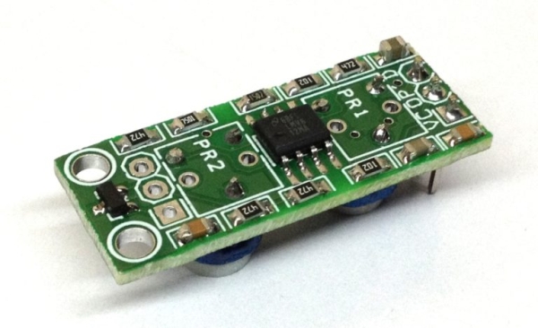
The output of DRV5053 is about 0.2V to 1.8V with the quiescent 1V at zero fields or no perpendicular flux to the sensing surface. In the non-linear configuration, the output range is limited either from 0.2V to 1V or from 1V to 1.8V. An Op-Amp stage is introduced in this design. It deals with the raw Hall sensor output signal with adjustable offset and scaling range. LMV612 op-amp used for signal conditioning. Actually, any fixed position along the full stroke of the magnet can be set as an offset point mechanically. When the relative position of the magnet and the Hall sensor is fixed at the designed offset point, the final output voltage can be adjustment by PR2. U1B is used as the amplitude amplifier stage with adjustable gain tuning by PR1. Also, there is an RC filter at the final output with R3 and C4. The actuator is fixed at a mid-point between the two ends of the stroke by a dual-spring system. Controlling by the foot, the actuator can go two sides of the stroke direction. The application requires the output to stay at about 1.1V when the actuator is at a balanced point (fixed offset point). When the foot strokes downside, the output goes from 1.1V down to ~0V. When the foot strokes upside, the output goes from 1.1V up to ~5V.
FEATURES
- Supply 5V DC
- Approximate linear response
- Adapt to wide magnet types and field range
- 0 to 5V full scale output ability
- Adjustable quiescent offset and gain
- Low power RRIO amplifier stage
- Cost-effective
- PCB Dimensions 32.09mm X 12.70MM
TUNING GUIDE
- Tuning PR2 for the designed fixed offset output
- Place the magnet to its MIN MAX stroke and tuning PR1 to get designed output range
- Release or return the fixed offset point, back to step 1 readjustment the offset point
- Back to step 2 to readjustment the offset output
- Repeat 1 to 4 steps to get both the designed offset the scaled output range.
- Note that the adjustment range of offset and scaling is also related to the mechanical magnet Configuration and the magnetic field. Do possible adjustment of the mechanical configuration if needed.
- The OpAmp parameters are also adjustable for special sensing range and output coverage. It is recommended to change R1 for extend offset adjustment ability and R8 for extend the gain range.
Read more: 0 TO 5V OUTPUT ANALOG HALL SENSOR FOR FOOT CONTROLLER
-
What is the quiescent output voltage of the DRV5053 at zero fields?
The output is about 1V when there are no perpendicular flux lines to the sensing surface. -
How does the circuit adjust the final output voltage?
The final output voltage can be adjusted by PR2 when the relative position of the magnet and Hall sensor is fixed at the designed offset point. -
What component is used as the amplitude amplifier stage?
U1B is used as the amplitude amplifier stage with adjustable gain tuning by PR1. -
What is the expected output voltage range when the actuator is balanced?
The application requires the output to stay at about 1.1V when the actuator is at a balanced point. -
How does the output change when the foot strokes upside?
When the foot strokes upside, the output goes from 1.1V up to approximately 5V. -
Can the resistor values be changed to extend adjustment capabilities?
Yes, it is recommended to change R1 to extend offset adjustment ability and R8 to extend the gain range.
