
Summary of Easy-DownloaderV1.1 for ATMEL89C2051
This article describes the Easy-Downloader V1.1, a low-cost tool for programming AT89C2051 and AT89C4051 microcontrollers. It features simple hardware with DOS and Windows software support, including single and double-sided PCB files and source code compatible with SDCC. The system automatically erases, writes, and verifies hex files without separate functions.
Parts used in the Easy-Downloader:
- AT89C2051 microcontroller
- AT89C4051 microcontroller
- 74LS373 8-bit latch
- DS275-like component
- 7805 voltage regulator
- LM317 voltage regulator
- 2N2222A transistor
- 2N2907A transistor
- DB-9 connector
- General purpose PCB or custom PCB
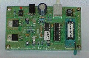
Build your own a personal writer forprogramming HEX code into Flash based microcontroller AT89C2051(2k) andAT89C4051(4k). Simple hardware and Easy use software in DOS and Windowversion. Single-side and double side PCB files included.sourcecode with sdcc version!
Introduction
The first version of the Easy-Downloaderwas designed in 1997 to be used as a tool for my students on building her/hisown microcontrollers circuit in the class ” Designing Microprocessors System”.The circuit features low-cost and easy use. The latest version V1.1 wasdesigned to be used with 2051 and the newest 4051 chips. There is no separatefunctions like other programmer e.g., blank check, erase, write. Simplytype say, c:\..>ez hello , the hex file “hello.hex” will then be programmedto the chip automatically. If the chip is not blank or the code is locked,it will erase first, then write and verify… that all.
Hardware
Figure 1 shows a circuit diagramof the Easy-Downloader. As shown, the circuit uses a 89C2051 with writer.hexfirmware, 74LS373 8-bit latch, DS275-like, 7805, LM317 and two transistors,2N2222A and 2N2907A. The programming voltage control circuit is the sameas recommended by ATMEL application note. It can be raised from 0V, 5Vand 12V by appropriated signal from P3. The 8-bit latch, 74LS373 providessome signal for selecting the programming modes. A byte to be programmedor read back is sent/received through P1. Incrementing address is doneby pulsing a positive pulse to XTAL pin. The circuit may be built usingsimple point-to-point soldering with a general purpose PCB( fish’s egglike PCB) or making PCB shown above, the file is Easy-v1.pcbProtel PCB version 2.76. The finished board should be tested without anychips; 1) +5V supply, 2) programming voltage 0V, 5V and 12V by connectingthe pin that control (P3.5 and D) 2N2222A and 2N2907 to +5V and/or GND.The adapter output should be approx. 15Vdc 100mA.
AcrobatPCB Files
Assuggested by a friend from Romania, Puiu Chiselita, to provide PCB imagein Acrobat file, so I have asked my friend, Jaroon Keawkhrua. He made withinan hour, thanks again for providing us, the Acrobat PCB file.
TOPLAYER (80kB) easy-v2t.pdf
BOTTOMLAYER (36kB) easy-v2b.pdf
COMPONENTLAYER (51kB) easy-v2o.pdf
Software
Two files that you shouldget are: writer.hex 4,871 bytes, the intelhex file firmware for 89C2051 chip ( the actual code size is 2021 bytes)and, ez.exe 20,800 bytes the uploader programrun on PC, send hex file to the downloader. The original writer.cprogram was written in ‘C’. To modify, it needs Micro C-compiler from DunfieldDevelopment System Ontario Canada with tiny memory model.
Functional Test
Use a given programmer (or readymade Easy-Downloader) write the writer.hex into the 2051 chip. Put theprogrammed 2051 chip to the board. Invoke any communication software with9600 baud, 8-data bit, no parity. Connect DB-9 to COM1, say, press enterkey, the title “Easy-Downloader V1.1 for ATMEL 89C2051/4051” would be appearedon the screen. type >s2048 ( set byte counter to 2k), then without the2051 chip in ZIF, type >r (read 2kB), on screen would show FFFFFFFFFFF…indicating corrected wiring for P1. If you put the chip having alreadyprogram inside, r command will show the hex code with the number of byteset by s command. Try e command to erase the entire program!! All done.Figure 2 shows example of using Xtalk program to test the board.
For more detail: Easy-DownloaderV1.1 for ATMEL89C2051
- How does the programmer handle non-blank chips?
If the chip is not blank or the code is locked, it will erase first, then write and verify automatically. - What software versions are supported?
The system uses easy-to-use software compatible with both DOS and Windows versions. - Can I modify the original writer.c program?
Yes, but modifying it requires the Micro C-compiler from Dunfield Development System Ontario Canada with a tiny memory model. - What is the recommended adapter output specification?
The adapter output should be approximately 15Vdc at 100mA. - How do you increment the address during programming?
Incrementing the address is done by pulsing a positive signal to the XTAL pin. - What command sets the byte counter to 2k?
Type s2048 to set the byte counter to 2k. - Does the circuit use separate functions like blank check?
No, there are no separate functions; it simply erases, writes, and verifies as needed. - What baud rate should be used for communication testing?
You should invoke communication software with 9600 baud, 8-data bit, and no parity.
