
Summary of CURRENT MEASUREMENT DATA LOGGER CIRCUIT ATMEL AVR, PIC
This article describes a current measurement data logger that records household power usage to an SD card. It utilizes microcontrollers like the Atmel AVR ATmega48/88/168 or PIC16C74 to process signals from current transformers and voltage detectors. The system calculates power consumption using analog multipliers, instrumentation amplifiers, and op-amps, displaying results on a GLCD or via PC software.
Parts used in the Current Measurement Data Logger:
- Current transformer
- Atmel AVR ATMEGA48 88/168-P microcontroller
- PIC16C74 microcontroller
- SD card
- GLCD display
- LMC6484A quad op-amp
- ADE7757
- AD623AN instrumentation amplifier
- Voltage divider
- Analog multiplier
- Low pass filter
- 12-bit A/D converter
Very high current of the current transformer and with microcontroller sensitive way measured to be recorded will be useful for source code with 2 sample application circuits one of the Atmel AVR ATMEGA48 88/168-P…Electronics Projects, Current Measurement Data Logger Circuit Atmel AVR, PIC “avr project, microcontroller projects, “

Very high current of the current transformer and with microcontroller sensitive way measured to be recorded will be useful for source code with 2 sample application circuits one of the Atmel AVR ATMEGA48 88/168-P used) based on the current (4kW) information on the SD card is able to record and chart GLCD the circuit can also view information on LMC6484A, ADE7757, AD623 used in the entegreleri
Other applications made by the software pic16c74 prepared with CCS C program via the PC displays current information
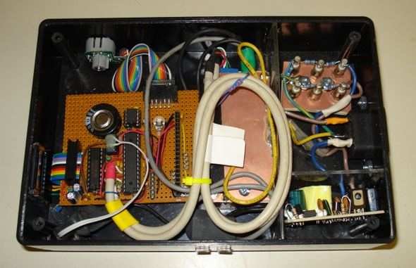
This device monitors household power usage and logs it to an SD card. A simple analog front-end amplifies the signals from voltage and current detectors and an ATmega168 microcontroller computes the power consumption using the formula P=V*I. voltage divider connected to an AD623AN instrumentation amplifier. LMC6484AIN quad op-amp is used for signal amplification.
Power Line Monitor power is calculated with an analog multiplier followed by a low pass filter to obtain the DC component (real power). These analog quantities are then fed to a 12-bit A/D converter driven by a ’77 PIC. The circuit gains get me a resolution of 5 Watts. As a result I can even see the effect of turning on one lamp.
Source : current-measurement-data-logger-circuit-atmel-avr-pic.rar
- What is the primary function of this device?
This device monitors household power usage and logs it to an SD card. - How does the circuit compute power consumption?
The microcontroller computes power consumption using the formula P=V*I. - Which components are used for signal amplification?
An AD623AN instrumentation amplifier and an LMC6484AIN quad op-amp are used for signal amplification. - Can the system detect small changes in power usage?
Yes, the circuit gains provide a resolution of 5 Watts, allowing users to see the effect of turning on one lamp. - What method is used to obtain real power?
Power is calculated with an analog multiplier followed by a low pass filter to obtain the DC component. - How is data displayed on the local unit?
The circuit can record and chart information on a GLCD. - Is there a way to view data on a computer?
Software prepared with CCS C program allows viewing current information via the PC. - What type of microcontroller options are supported?
The project supports Atmel AVR ATMEGA48 88/168-P and PIC16C74 microcontrollers.
