
Summary of Ardu-pong! the Arduino based pong console
This project builds a polished, Atari-themed Pong console using an Arduino. The author improves upon existing designs by creating a user-friendly system housed in a repurposed digital TV receiver and later a mint tin. It features a real Atari joystick for controls rather than potentiometers, connects to a TV via RCA, and uses a serial port for input.
Parts used in the Arduino Pong Console:
- Arduino
- Atari joystick
- RS232 socket
- RCA jack
- 1Kohm resistor
- 330 ohm resistor
- Power switch
- Digital TV receiver enclosure
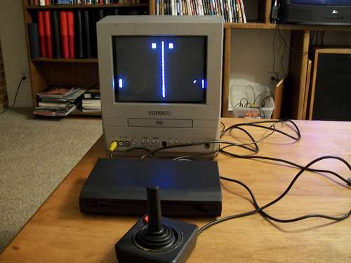 A while back the instructables robot made a post on Facebook about some guys who played pong on an Arduino (http://wayneandlayne.com/projects/video-game-shield/games/#pong)
but after looking around, i saw that everyone who did this was only worried about making it work. and often resulted as a very hard to use system with only potentiometers to use as controllers. so in my attempt at this, i decided that it needs to be much more polished if it is ever to be something of use. so heres how i did it:
UPDATE! ive managed to shink it down into an entire atari themed mint tin! check it out here
Step 1 Get the stuff.
so to do this, we are going to need a couple of things.
first off, we obviously need an Arduino, we are also going to need an atari joystick, a rs232 socket, a rca jack, 1Kohm resistor and a 330 ohm resistor, a switch for power, and something to cram all the guts into , i decided to use a busted digital tv receiver as my enclosure
first off, we obviously need an Arduino, we are also going to need an atari joystick, a rs232 socket, a rca jack, 1Kohm resistor and a 330 ohm resistor, a switch for power, and something to cram all the guts into , i decided to use a busted digital tv receiver as my enclosure
Step 2 Hack the enclosure.
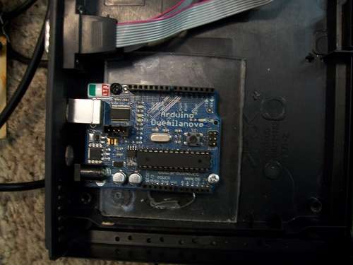 now take your chosen enclosure and take it apart and remove all the circuit boards and junk you otherwise will not need, then mount your Arduino against the backside of the enclosure and drill a hole large enough for a usb cable to fit through, then cut out a hole for the serial port to be mounted through.
Step 3 Install the rca jack.
before we install the rca jack we need to freeform the following circuit off of the pins of the rca jack .
then we can drill a hole in the back of the enclosure for the rca jack to come through and then glue it in place.
then we can drill a hole in the back of the enclosure for the rca jack to come through and then glue it in place.
Step 4 Wire the serial port
now we have to wire the serial port to the pins on the arduino so we can get input from the joystick.
so using the following pinout, connect the following to the corresponding pins on the Arduino
pin1 up, to Arduino pin 7
pin2 dn, to Arduino pin 6
pin6 fire,to Arduino pin 2
For more Detail: Ardu-pong! the Arduino based pong consolebased
- Why did the author create this project?
The author wanted a more polished and usable system compared to previous hard-to-use designs that relied on potentiometers. - What enclosure was originally chosen for the build?
A busted digital TV receiver was selected as the initial enclosure before shrinking the project into a mint tin. - How is the Atari joystick connected to the Arduino?
Pin 1 goes to Arduino pin 7, Pin 2 goes to Arduino pin 6, and Pin 6 goes to Arduino pin 2. - What components are required to wire the serial port?
You need to connect the serial port pins to specific Arduino pins to receive input from the joystick. - Can the final project fit into a smaller container?
Yes, the project was successfully shrunk down into an entire Atari themed mint tin. - What type of controller does this system use?
The system uses an Atari joystick instead of the potentiometers found in other similar projects. - How do you prepare the digital TV receiver for the build?
You must take it apart, remove unnecessary circuit boards, mount the Arduino to the backside, and drill holes for cables. - What is the purpose of the RCA jack in this setup?
The RCA jack is installed to output the video signal so the game can be played on a TV.
