Summary of Generating AUDIO ECHO using Atmega32 microcontroller
This article describes an audio echo generator project using an ATmega32 microcontroller. The system captures voice via an electret microphone, processes the signal through an ADC with amplification and level shifting, and applies digital feedback within a 1900-byte circular buffer to create a delay effect.
Parts used in the Audio Echo Generator:
- ATmega32 microcontroller
- Electret microphone
- Analog-to-Digital Converter (ADC)
- Amplification circuit
- Level shifting circuit
- 1900-byte circular buffer
Introduction:
But now I can do this very easily by a simple digital signal processing using a microcontroller. It’s concept is very simple, ie we need to apply a proper delayed feedback in digital samples with in a circular buffer. I did this using an atmega32 microcontroller and it worked fine. This is simple but really an interesting project. Not only an echo, but we can do a lot of fun with this type of small DSP experiments if we have considerably large RAM in the mcu…
(video demo of echo generation using atmega32)
Working:
I am using an Atmega32 microcontroller for the purpose. It is having RAM of 2KB and an ADC which is enough for demonstrating the concept of echo generation. An electert mic is used for capturing the voice. It is introduced to ADC with proper amplification and level shifting, which are more critical for the perfect operation.
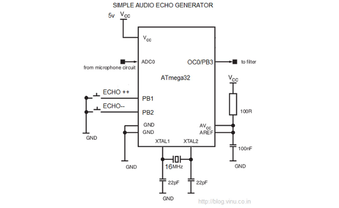 Now the ADC module inside the AVR will convert the analog signal to digital signal at a particular sampling rate(which we can decide). Now a 1900byte circular buffer is introduced. Our first aim is to make a delay in input and output audio. So, we can do one thing, ie we can populate the buffer from one end and we can read the buffer from another point so that there will be a delay! So how to make this delay to it’s maximum? I think it will be better to explain it via a diagram. For More Detail: Generating AUDIO ECHO using Atmega32 microcontroller
- How is the echo effect generated?
An echo is created by applying proper delayed feedback in digital samples within a circular buffer. - What microcontroller is used for this project?
The project uses an Atmega32 microcontroller which has 2KB of RAM. - Which component captures the voice input?
An electret mic is used for capturing the voice. - What are the critical steps before the ADC conversion?
The signal requires proper amplification and level shifting for perfect operation. - How does the system achieve maximum delay?
Delay is achieved by populating the buffer from one end and reading it from another point. - What size circular buffer is implemented?
A 1900 byte circular buffer is introduced to store the digital samples. - Can this concept be expanded for other effects?
Yes, similar DSP experiments can be done if the MCU has considerably large RAM.