Summary of Multitasking in AVR (A demo to run 7 tasks on an atmega32)
This article demonstrates a Round-Robin time-sharing multitasking system on an ATmega32 AVR microcontroller. It runs seven independent tasks, including one software PWM and six toggling tasks, by dividing 2KB of RAM into 300-byte stacks per task. A timer interrupt triggers context switching: the ISR saves CPU registers and status to the stack, updates a stack pointer backup table at RAMEND, loads the next task's stack pointer, and resumes execution. This creates the illusion of parallel processing despite single-core time-slicing.
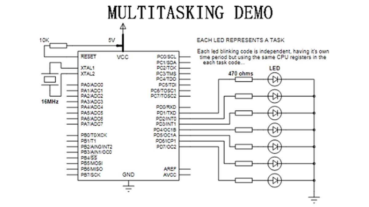
Parts used in the Round-Robin Multitasking Demo:
- ATmega32 microcontroller
- Timer interrupt mechanism
- RAM memory (2KB total)
- Stack space (300 bytes per task)
- Task index storage area
- Stack pointer backup table (50 bytes reserved near RAMEND)
- LED indicators (7 LEDs representing tasks)
Introduction:
Scheduling algorithm used: Round-robin (RR)
(one of the simplest scheduling algorithm)
Working:
Now, when the task1 is interrupted by the switching timer interrupt, as said above, it push all CPU registers and the status register. Then it checks the ‘task index’ which will be there on the RAMEND. From the task index, we get the task number and thus we can obtain the exact location on the stack backup table on which the stack pointer value is to be stored. Also we can get the next task’s stack pointer value relative to the location where we stored the current one and that is loaded to the stack pointer.
So, we got the stack pointer of the next task. Now, we can pop the status register and all the cpu registers and finally the RETI instruction will enable the global interrupt and then divert (jump to new PC value) the cpu to resume the next task…. This repeats with a time slot in range of micro seconds and thus we feel all the tasks are running in parallel and also purely independent even though they are using the same cpu registers in common.
Here are some pictures which I drawn to make the above explanation more clear. It represent the RAM usage for the stack pointer backup table and the process stack.
For more detail: Multitasking in AVR (A demo to run 7 tasks on an atmega32)
- What scheduling algorithm is used in this project?
The project uses the Round-Robin (RR) scheduling algorithm. - How many independent tasks are executed simultaneously?
The system executes seven independent tasks. - How much RAM is allocated to each task?
Each task receives approximately 300 bytes of RAM for its stack. - What happens when the timer reaches the compare value?
It triggers an interrupt that initiates context switching between tasks. - Which register is pushed manually during the interrupt service routine?
The status register is pushed onto the stack manually because the AVR does not do it automatically. - Where is the stack pointer backup table stored?
It is stored in a reserved 50-byte area starting from RAMEND. - Does Task1 use the same hardware resources as other tasks?
Yes, all tasks share the same CPU registers but run independently via time-slicing. - What instruction enables global interrupts after resuming a task?
The RETI instruction enables global interrupts and diverts the CPU to the next task.